The Expert Summit for a Sustainable Future Mobility
Only together we can create a sustainable future mobility. CO2 reduction is critical for automotive drivetrain. Here the battery electric drive using renewable energy is the focus. What can we do to increase efficiency and reliability, reduce cost and at the same time reduce the upstream CO2?
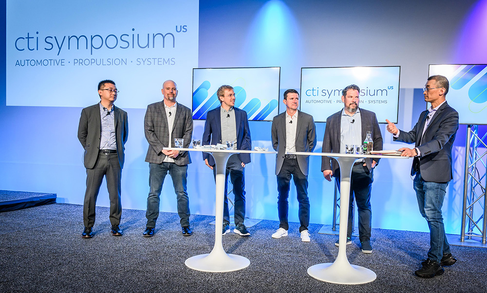
At CTI SYMPOSIUM the automotive industry discusses the challenges it faces and promising strategies. Latest solutions in the fields of electric drives, power electronics, battery systems, e-machines as well as the manufacturing of these components and supply chain improvements are presented. For the bigger picture market and consumer research results as well as infrastructure related topics supplement the exchange of expertise.
CTI SYMPOSIA drive the progress in individual and commercial automotive transportation. Manufacturer, suppliers and institutions are showing how to master the demanding challenges.
Specials
10 Deep Dive Sessions on Passenger Cars and Commercial Vehicles
Government/Industry Panel
OEM & Supplier Panels
Truck Panel
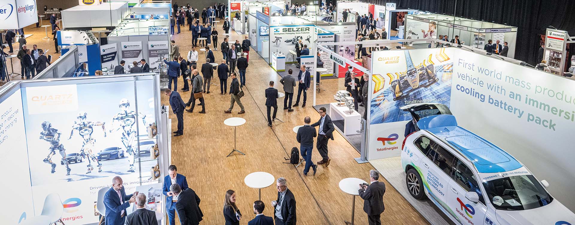
Explore the latest products and innovations in the accompanying exhibition
Ride & Drive: Enjoy a full-feature tech experience in series and demo vehicles
Women@CTI Special Program
NEW: Start-up Area
Extensive networking opportunities
Outstanding evening event
Topics
Transformation of the Automotive and Supplier Industry
Markets and Analysis
Latest EV and Plug-in Hybrid Propulsion Technology
M.Sc. Kai von Schulz, M.Sc. Tilmann Linde, Prof. Dr.-Ing. Steffen Jäger Furtwangen University, Institute for Product and Service Engineering Reducing the sound emitted by the vehicle and the noise perceived by the passengers is an essential part of the development of modern (e-)vehicles. Bearings are crucial to the transmission of vibrations within the vehicle powertrain. […]
M.Sc. Kai von Schulz, M.Sc. Tilmann Linde, Prof. Dr.-Ing. Steffen Jäger
Furtwangen University, Institute for Product and Service Engineering
Reducing the sound emitted by the vehicle and the noise perceived by the passengers is an essential part of the development of modern (e-)vehicles. Bearings are crucial to the transmission of vibrations within the vehicle powertrain. This article presents a method for studying the impact of external bearing damping on acoustic properties. For this purpose, damping elements between the outer bearing ring and the gearbox housing of a gearbox used in electric vehicles are introduced, and parameters relevant to damping are varied by means of design of experiments.
Noise sources and sound transmission
At first, the noise sources that occur in a gearbox for electric vehicles will be identified. The gear mesh is determined as one of the primary sources of noise. The vibrations generated by the gear mesh are transferred through the shafts, the bearings, and the gearbox housing [1]. The design and material of the gearbox housing play a crucial role in how these vibrations are transmitted and whether they are dampened or amplified [2]. The vibrations can cause resonance in the housing, amplifying the noise emitted from the gear mesh. The air-borne sound emission occurs when the vibrations from gear mesh and structure-borne sound radiate into the surrounding environment. Due to deviations in the ideal meshing, a transmission error occurs between the driving and driven gear. The transmission error is primarily influenced by the manufacturing tolerances, variations in gear tooth geometry, and operational conditions such as load and speed [3]. The design and manufacturing quality of the gears have a considerable impact on their acoustic characteristics [4]. Moreover, the surface roughness of the gear teeth can influence friction and noise generation [5].
Bearings not only transmit the vibrations introduced by the gear mesh, but can also be a source of noise themselves. The primary sources of noise in bearings occur from various factors including design, manufacturing imperfections, operational conditions, and inadequate maintenance [6]. Factors such as load, speed and alignment are of significant importance. Imperfections in the surface finish of the raceways and the balls or rollers, as well as their roundness, can result in an uneven distribution of loads across the bearing surfaces [7]. The presence of high loads or speeds can exacerbate any existing imperfections in the bearing [8].
Finally, the electric motor can also be regarded as a source of perceptible noise. Electric motors, while quieter than internal combustion engines, introduce their own sources of noise, particularly through torque ripple and electromagnetic interference [9]. Torque ripple refers to the variation in torque output as the motor rotates, which can induce additional vibrations in the gearbox [10]. In addition, electromagnetic interference can cause vibrations in the motor’s components, which may be transmitted to the gears through the coupling, thereby further worsening the acoustic behaviour [11].
Potential noise reduction measures
Following the overview of the noise generation mechanisms within the gearbox, it is evident that specific, targeted measures are required to mitigate the associated noise emissions effectively. The primary noise sources, as described in the previous section, are main areas of concern. Targeted measures in these areas can significantly improve the acoustic behaviour of electric vehicle gearboxes. The authors have examined a wide range of measures for reducing the noise of drive systems [4, 12]. The focus of this article is on damping of the excitation by both the tooth mesh and the ball bearings.
The modification of bearing damping characteristics has the potential to result in a reduction in noise levels [13]. Incorporating damping inserts within or around the bearings of a gearbox is an effective method to absorb vibrations at their source before they are transmitted to the gearbox housing. Materials commonly used for these inserts include elastomeric compounds, viscoelastic polymers, and soft metals which are tuned to absorb specific frequencies of vibrations that are prevalent in gearbox operations [14]. These damping elements are usually placed in the most effective locations in the bearing assembly, where they can absorb the vibration energy resulting directly from the interaction between the rolling elements and the raceways.
Design of experiments on external bearing damping configurations
Design of Experiments (DoE) is a statistical approach to study the impact of multiple factors on the systems performance. In the context of analysing external damping of roller bearings, DoE is applied to evaluate how different parameter sets affect the transfer of the vibrations. DoE is particularly useful in this context, as it enables the identification of the most influential factors affecting both noise levels and efficiency, as well as the optimal combination of these parameters.
The variables in this case are the number of O-rings, their rigidity and the cord thickness of the O-rings, and whether additional oil is pressed into the gaps or not. By allowing simultaneous variation of parameters, DoE not only saves time and resources but also uncovers interactions between these parameters that might otherwise remain hidden. In this way, DoE provides a more comprehensive understanding of how the variables work together to influence the system’s behaviour, revealing possible synergies or trade-offs between different parameters. Here, the focus is on the system’s response in terms of its structure-borne and airborne sound emissions. Additionally, the system efficiency is analysed. For example, reducing the stiffness of the O-rings may reduce the transferred vibration, but it may also reduce efficiency due to a higher transmission error in the tooth mesh. The application of DoE allows the reduction of the number of experimental runs while maintaining the comprehensive coverage of the interactions and effects of all factors within the specified range. This efficiency in test design is critical in experimental research involving complex mechanical systems, where a large number of tests could be impractical due to time, cost, or resource constraints.
Physical study
To evaluate the presented measure of outer bearing damping, an existing high-speed gear test rig (cf. Figure 1) is being converted so that different parameter sets of outer bearing damping can be tested for their effectiveness under different operating conditions, such as speed and torque.
Fig. 1 Gear pair test rig.
For this purpose, the bearing seats have been modified to allow the use of up to three commercially available nitrile rubber O-rings. In addition, it is possible to fill the spaces between the O-rings with oil and apply an overpressure. Figure 2 shows a schematic illustration of the design.
Figure 2 CAD geometry of outer bearing damping design.
In this study, the experimental parameters are varied within specific ranges, providing valuable insights into their effects on system behaviour. Various tests are carried out at different torques and speeds in the range between 0 and 6000 rpm and 0 and 45 Nm. The measurement results are analysed at static operating points. The experimental design includes varying the number of O-rings from 1 to 3 and varying the stiffness of the O-rings between 70 and 90 Shore. In addition, the cord thickness of the O-rings is varied between 1.8 mm and 2.8 mm and whether additional oil is injected into the gaps is also considered as a binary factor (yes/no). Through the application of DoE, this study aims to determine the optimal combination of these factors to achieve an appropriate damping characteristic: significantly reducing noise while maintaining high efficiency.
Once the test rig has been converted and the measurement campaign has been completed, the most promising damping elements will be further optimised.
Authors
M.Sc. Kai von Schulz: Kai.vonSchulz@hs-furtwangen.de
M.Sc. Tilmann Linde: tilmann.linde@hs-furtwangen.de
Prof. Dr.-Ing. Steffen Jäger: steffen.jaeger@hs-furtwangen.de
References
[1] Tosun, M., Yildiz, M. u. Ozkan, A.: Investigation of Gearbox Noise and Comparison of Varying Transfer Path Analysis Methods. SAE Technical Paper 2017-01-1867, 2017
[2] Amaral, D. R., Ichchou, M. N., Kołakowski, P., Fossat, P. u. Salvia, M.: Lightweight gearbox housing with enhanced vibro-acoustic behavior through the use of locally resonant metamaterials. Applied Acoustics 210 (2023), S. 109435
[3] Heider, M. K.: Schwingungsverhalten von Zahnradgetrieben. Beurteilung und Optimierung des Schwingungsverhaltens von Stirnrad- und Planetengetrieben. Zugl.: München, Techn. Univ., Diss., 2012. Dissertationen der FZG / Forschungsstelle für Zahnräder und Getriebebau, Technische Universität München, Bd. 185. München: Verl. Dr. Hut 2012
[4] Schulz, K. von, Linde, T. u. Jäger, S.: Profile Modifications for Gears and their Effect on the NVH Behaviour of an Electric Vehicle Gearbox. 2024 Stuttgart International Symposium on Automotive and Engine Technology. Stuttgart 2024
[5] Zhao, X. u. Vacca, A.: Analysis of continuous-contact helical gear pumps through numerical modeling and experimental validation. Mechanical Systems and Signal Processing 109 (2018), S. 352– 378
[6] Adamczak, S., Stępień, K. u. Wrzochal, M.: Comparative Study of Measurement Systems Used to Evaluate Vibrations of Rolling Bearings. 1877-7058 192 (2017), S. 971–975
[7] Mohd Yusof, N. F. u. Ripin, Z. M.: Analysis of Surface Parameters and Vibration of Roller Bearing. Tribology Transactions 57 (2014) 4, S. 715–729
[8] Wang, Z., Yang, J. u. Guo, Y.: Unknown fault feature extraction of rolling bearings under variable speed conditions based on statistical complexity measures. Mechanical Systems and Signal Processing 172 (2022), S. 108964
[9] Gong, C., Zhang, P., He, S. u. G S J, G.: E-motor NVH Analysis for PWM Induced Current Ripples in EV Applications. 2022 IEEE Energy Conversion Congress and Exposition (ECCE). IEEE 2022, S. 1–5
[10] Novak, W.: Geräusch- und Wirkungsgradoptimierung bei Fahrzeuggetrieben durch Festradentkopplung, Universität Stuttgart Dissertation. Stuttgart 2010
[11] Kim, S. J., Kim, K., Hwang, T., Park, J., Jeong, H., Kim, T. u. Youn, B. D.: Motor-current-based electromagnetic interference de-noising method for rolling element bearing diagnosis using acoustic emission sensors. Measurement 193 (2022), S. 110912
[12] Schulz, K. von, Linde, T. u. Jäger, S.: Measures to reduce the noise emission of a gearbox for electric vehicles. Tagungsband Tribologie-Fachtagung 2024. 2024, S. 394–403
[13] Tsuha, N. A. H. u. Cavalca, K. L.: Stiffness and damping of elastohydrodynamic line contact applied to cylindrical roller bearing dynamic model. Journal of Sound and Vibration 481 (2020), S. 115444
[14] Turnbull, R., Rahmani, R. u. Rahnejat, H.: The effect of outer ring elastodynamics on vibration and power loss of radial ball bearings. Proceedings of the Institution of Mechanical Engineers, Part K: Journal of Multi-body Dynamics 234 (2020) 4, S. 707–722
Electric vehicles are revolutionizing the automotive industry in a way that has not been seen since the seatbelt became mandatory in 1967. Competition among OEMs is increasing and the modern day ‘race to the moon’ is underway, lead by manufacturers such as Volkswagen, Ford, GM and Volvo as they roll-out EV & hyrbid models off […]
Electric vehicles are revolutionizing the automotive industry in a way that has not been seen since the seatbelt became mandatory in 1967. Competition among OEMs is increasing and the modern day ‘race to the moon’ is underway, lead by manufacturers such as Volkswagen, Ford, GM and Volvo as they roll-out EV & hyrbid models off the assembly line. Not to be forgotten are more than 100 ambitious startups looking to make a name in the automotive world. Take a couple steps back in the supply chain and there are countless automotive suppliers watching the competition unfold, excited for the new market opportunities this will bring.
Metal stamping companies make up a large part of the automotive suppliers wondering where they will fit into the electric vehicle landscape. Many likely wondering what their new identity will be 10 years from now. It is certain that metal stampings will remain a major part of the automotive supply chain as we transition to EV, but the type of components that will be stamped is the question mark. A reputable stamping supplier that once specialized in powertrain components may soon find their stamping presses being used for battery trays and EV motor laminations. In order to stay agile and be prepared for any type of stamping coming through the pipeline, a supplier needs two things: First, the the willingness and unity to change even if it’s outside their niche, and second, the necessary equipment and processes to support the evolution.
In the case of A.J. Rose Manufacturing Co., they recently invested in new equipment intended to support the markets of the future. That equipment is a newly-built servo press from Aida. This will be the 58th press at A.J. Rose and also the largest press at 1375 tons. At this tonnage, it opens doors to new markets and product lines with the ability to to produce larger parts and run thicker material. They are adapting to the market, not expecting the market to adapt to them. At a bed size of 191” x 70” and a 20 inch stroke, A.J. Rose will offer more capability to their customers looking for large stampings. A purchase of this magnitude was a decision based partly on current necessity and partly on strategic forecasting of future demand. A.J. Rose is positioning themselves to support the increased sourcings in battery plates, battery boxes, battery trays, large brackets and similar housing components that are becoming popular in the EV space. In order to be nimble in these new markets, the press will be capable of running transfer tools or progressive tools, and the servo motor allows for variable speeds and advanced forming capabilites, such as dwelling at the bottom of the stroke. These features make this a Swiss-Army knife of stamping presses, capable of forming metal into unique geometries in a wide range of size and thickness. This is what puts a supplier in a position for growth, making them attractive with an exisiting customer or one brand new.
A wide range of OEM customers turn to A.J. Rose for high-precision, high-quality metal stampings, therefore it is crucial to maintain their reputation as an innovator in the industry. Having such a reputation associated with their brand helps to establish credibility and lends to partnerships with up-and-coming EV startups. Out of many startups gaining momentum in the EV space, it will certainly narrow down to a short list of companies that rise to the top and begin serious competition in the pure EV markets.
A large pit is dug roughly 20 feet into the ground to prepare for the press. Supporting walls are poured from cement within the hole and a connection is made to the existing underground scrap-removal conveyer (right side).
A gantry system is used to support the weight of the press as it is assembled and secured to the foundation.
The press is assembled and secured in the pit. Capacitors are installed in the back.
Gabriela Achtenova, Michal Jasný, Jiri Pakosta, Rômulo do Nascimento Rodrigues Center of Vehicles for Sustainable Mobility, Czech Technical University in Prague Dog clutches are cost-effective but often suffer from angular backlash, causing discomfort. A novel, patented design has been developed to eliminate this issue using a purely mechanical blocking mechanism. This design, fully interchangeable with […]
Gabriela Achtenova, Michal Jasný, Jiri Pakosta, Rômulo do Nascimento Rodrigues
Center of Vehicles for Sustainable Mobility, Czech Technical University in Prague
Dog clutches are cost-effective but often suffer from angular backlash, causing discomfort. A novel, patented design has been developed to eliminate this issue using a purely mechanical blocking mechanism. This design, fully interchangeable with conventional mechanisms, requires no extra modifications but needs an external synchronization system.
Featuring innovative gearshift dogs and blocking mechanisms, it was tested with two prototypes on test benches. The results showed the design’s effectiveness, and robustness especially for hybrid and electric vehicles, addressing key shortcomings of traditional clutches.
Introduction
Greenhouse gases, CO2 regulations, alternative fuels, and vehicle electrification are critical issues driving the rapid growth of hybrid (HEV) and electric vehicles (EV) [1]. This shift demands innovative solutions in automotive engineering. This research focuses on developing a new gearshift mechanism to meet these demands. In HEVs and EVs, the electric motor can act as an external synchronization mechanism, potentially reducing costs. Parallel hybrids, requiring a wide range of gear ratios, benefit from cost-effective gearboxes like manual parallel shaft gearboxes (MT) or automated versions (AMT) [2][3]. These gearboxes commonly use synchronizers, a prevalent gearshift mechanism in passenger cars [4].
This research aims to replace the synchronizer with a new, cost-effective gearshift mechanism that eliminates the need for synchronization while maintaining or surpassing the synchronizer’s functions [5]. Typically, a dog clutch is the simplest gearshift mechanism for constant mesh gears but has been limited by driving comfort and NVH (Noise, Vibration, and Harshness) concerns. In electric powertrains, NVH issues include gear whine and gearshift mechanisms [4],[6]. Reducing angular backlash is crucial for minimizing NVH, a feature of the new mechanism, while ensuring cost-effectiveness and compactness. More compact gearboxes tend to be stiffer, further reducing NVH [7].
This research introduces a patented dog clutch design addressing angular backlash, a common issue in traditional mechanisms [7]. Using a purely mechanical blocking system, it minimizes backlash and improves shifting quality. The form of dogs enables very fast disengagement of the speed even under load. Rigorous prototype testing confirmed its functionality, durability, and comfort, making it suitable for vehicle gearboxes.
Final design of dog clutch with blockchain mechanism
The clutch assembly (Figure 1) includes a hub (1) on the gearbox shaft, a sliding gear (2) that moves axially to engage gears, a gearshift sleeve (3) for controlling movement, and a blocking ring (4) to secure the sliding gear in positions. The sliding gear is split into two halves connected by screws (5) and pins (6). One blocking ring locks the sliding gear in all three positions (engaged/neutral/engaged) and secures the gearshift sleeve in neutral. No changes to the standard MT/AMT gear selector mechanism are needed. The design’s uniqueness is confirmed by Patent No. 307443[8] and the utility model „Schaltungskupplung“ [9]. Following design optimization, prototypes of dog clutches with a blocking mechanism were produced. Two clutches for the MQ200 gearbox were made to engage 1st, 2nd, 3rd, and 4th gears, see Figure 2. The prototype production was funded and supported by ŠKODA AUTO.
Gearshift process
The blocking ring stays concentric with the hub due to its constant contact with the sliding gear or gearshift sleeve. With six contact points, the ring maintains its shape during compression. To prevent uneven deformation, which could interfere with gear movement and cause excessive wear, the ring’s ends are bent inward. Figure 3 illustrates the gearshift process, where shifting the right gear involves: Position 1 – neutral:Black arrows show axial backlash between the sliding gear and the gearshift sleeve. The blocking ring holds both components – sliding gear (upper) and sleeve (lower) – in neutral; Position 2 – engagement preparation:The sleeve moves right, compressing the blocking ring, while the sliding gear remains in neutral until backlash is resolved; Position 3 – engagement in process:With backlash removed, the sleeve pushes the sliding gear right, and the blocking ring stays compressed; Position 4 – engagement termination:The sliding gear reaches its maximum position, engaging the gearshift dogs. Both components stop moving axially, and the blocking ring is no longer compressed; Position 5 – engaged: The blocking ring expands back to its original position, fitting into the sliding gear’s groove, preventing clutch disengagement due to torque;
Position 6 – disengagement preparation:The sleeve moves left to compress the blocking ring. Axial backlash is present, keeping the sliding gear engaged; Position 7 – disengagement in progress:The blocking ring is fully compressed, backlash is gone. The sleeve moves the sliding gear to
Position 8 – Disengagement Termination: The sleeve reaches neutral, but the sliding gear remains slightly engaged due to kinetic energy. The decompressing blocking ring helps move the gear to neutral; Position 9 – Neutral:The dog clutch returns to the neutral position, same as Position 1.
Prototypes of the clutch were designed for the MQ200 gearbox, where the blocking ring withstands axial forces up to 2 kN during dog engagement, transferring a maximum torque of 200 Nm. The force needed to engage and disengage the clutch via the gearshift sleeve is about 45 N, which is well within permissible limits and comparable to manual shifting forces. The sliding gear and gearshift sleeve have been optimized for powder metallurgy. For the sliding gear, only grooves for the blocking rings and threads on one half need machining, while the gearshift sleeve requires machining of the inner groove for the neutral position. The outer groove, for the gear selector fork, is for prototype compatibility and can be omitted in future designs. No additional parts are required between the sliding gear and gearshift sleeve, ensuring concentric alignment with the hub. The blocking ring is fixed securely and cannot rotate around the shaft axis due to the pin.
Verification of the dog clutch
The fulfillment of the requirements for the dog clutch with a blocking mechanism needed to be validated against the design specifications. First experiments were static to verify the shift force and unwanted disengagement. The resulting gearshift force required to compress the blocking ring was measured to be 45 N.
Further was experimentally tested that the blocking ring functions as intended, preventing unwanted disengagement of the clutch.
The dynamic tests were dedicated for verification of function and for endurance tests. The first phase of clutch prototype testing used an inertia test bench with the output shaft connected to a large inertia disc. Tests focused on smooth shift sleeve movement and proper engagement / disengagement of the dogs. No unexpected behavior was observed.
The gearbox was connected to the gearshift robot on the inertia test stand, and gearshifts were performed with various input parameters. Mismatch speed was controlled by the difference between the stationary input shaft and the rotating wheel or by gear ratios between two gears. Figure 4 shows data from a gearshift with 3rd gear engaged at a mismatch speed of 30 RPM. The gearshift process began at 0.96 s, with rising displacement and force curves. A sharp drop in force at 1.02 s indicated compression of the blocking ring, allowing the sliding gear to move. The force increased as the dogs engaged, and by 1.08 s, engagement was complete. The gearshift took about 60 ms.
To proceed with dynamic check of the blocking mechanism, the gearbox was moved to dynamometric test bench. The function for the 3rd and 4th gears were performed with positive result. Due to test bench capacity 1st and 2nd speed were not tested.
Service life (endurance) tests were conducted for the 3rd and 4th gear clutches on the inertia test bench, with each gear being shifted 180,000 times and the gearbox output set to 89 RPM. This low speed simulated a mismatch speed of around 140 RPM, optimizing the gearshift process and eliminating the need for external synchronization. Each shift took just over 2 seconds, resulting in 220 hours of continuous testing per clutch and blocking ring.
Conclusion
The new patented dog clutch with a blocking mechanism enhances efficiency and reduces costs for electric and hybrid vehicles. It offers minimal angular backlash (less than 0.1°) and can disengage under load, improving shifting comfort and torque transmission. This purely mechanical design is compatible with standard gear selectors, including sequential shifting, and requires no additional modifications. The clutch’s blocking ring withstands high axial forces, preventing unwanted disengagement. Prototypes, tested in a standard five-speed gearbox, demonstrated up to 30 mm axial space savings compared to conventional synchronizers. The design supports effective serial production using powder metallurgy and has proven durability with a service life of 700,000 cycles.
References
[1] PILLOT, Christophe. The Rechargeable Battery Market and Main Trends 2020-2030. Lyon: Avicenne Energy, 2022.
[2] HOFMANN, Peter. Hybridfahrzeuge – Ein alternatives Antriebssystem für die Zukunft. Switzerland : Springer, 2014. Second edition. ISBN: 978-3-7091-1780-4
[3] NAUNHEIMER, Harald et al. Automotive Transmissions: Fundamentals, Selection, Design and Application. Berlin : Springer-Verlag, 2011. ISBN 978-3-642-16216-8.
[4] FISCHER, Robert et al. The Automotive Transmission Book. Switzerland: Springer International Publishing, 2015. ISBN 978-3-319-05262-5.
[5] MEHRGOU, Mehdi et al. NVH Aspects of Electric Drives-Integration of Electric Machine, Gearbox and Inverter. 2018. SAE Technical Paper 2018-01-1556. doi: 10.4271/2018-011556. ISSN 0148-7191.
[6] Wu,G.,Zhang, X.,& Dong, Z. (2015). Powertrain architectures of electrified vehicles: Review, classification and comparison. Journal of the Franklin Institute, 352(2), 425–448. doi: 10.1016/j.jfranklin.2014.04.018
[7] TŮMA Jiří. Vehicle Gearbox Noise and Vibration. New Delhi: John Wiley & Sons, Ltd., 2014. ISBN 978-1-118-35941-9.
[8] ČESKÉ VYSOKÉ UČENÍ TECHNICKÉ V PRAZE, FAKULTA STROJNÍ. Řadící spojka. Inventors: JASNÝ, M., G. ACHTENOVÁ and J. PAKOSTA. File No. MPT F 16 D 11/10. Patent No. 307443. 22. August 2018. Czech Office of Industrial Property. Patent.
[9] SCHECHISCHE TECHNISCHE UNIVERSITÄT IN PRAG, FAKULTÄT FÜR MASCHINENBAU. Schaltungskupplung. Inventors: JASNÝ, M., G. ACHTENOVÁ and J. PAKOSTA. IPC-Class F16D 11/00 (2006.01). File No. DE: 20 2018 103 633.5. 26. June 2018. Deutsches Patent- und Markenamt. Utility model.