For more than five decades, North American powertrain strategy was shaped more by regulation than by the road. Compliance was king, setting the pace by driving investment cycles, product plans, and engineering priorities for the region.
But this is changing. And driven by this change, we find ourselves coming back to the only question that ultimately matters: What does the customer actually want?
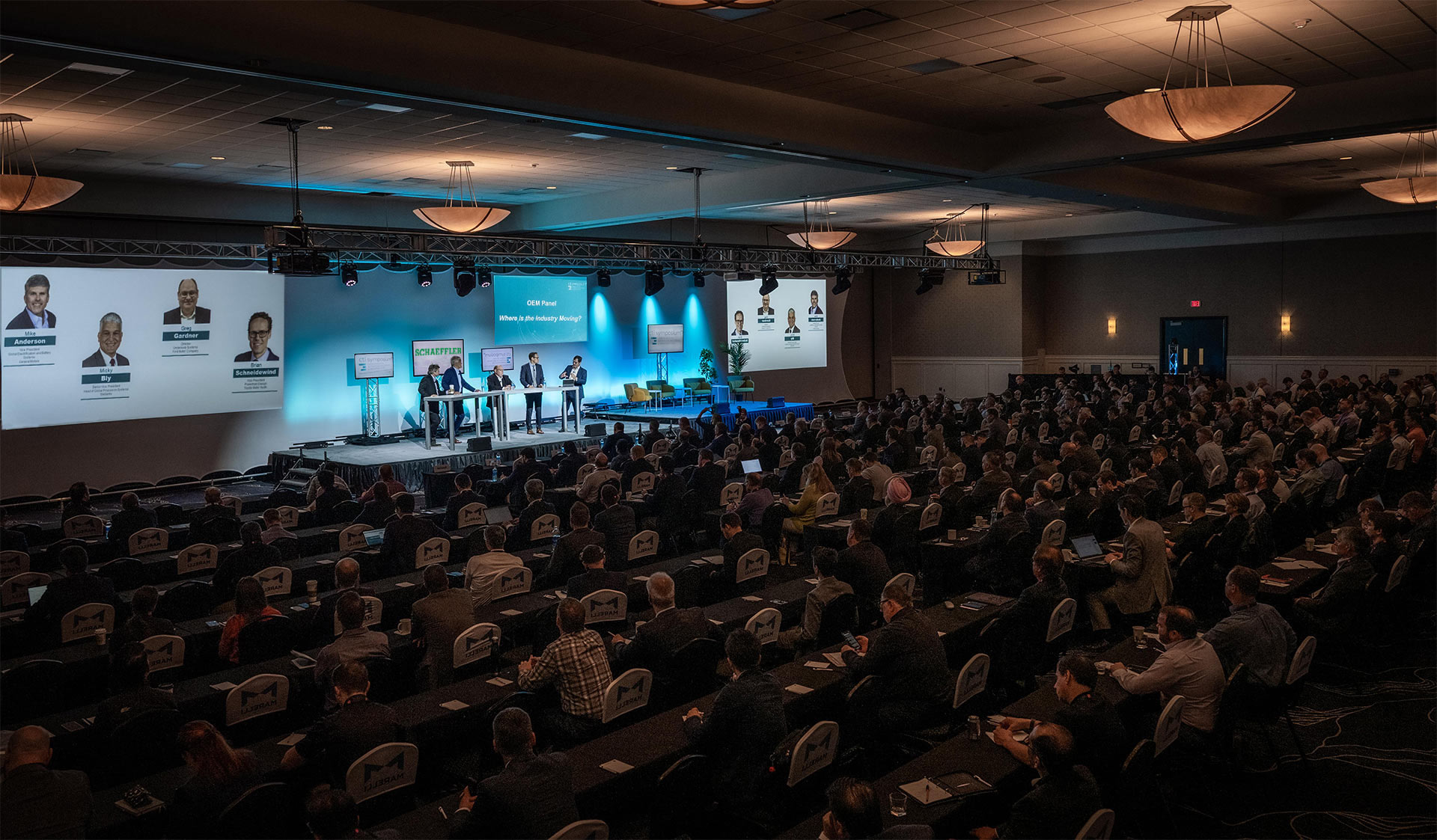
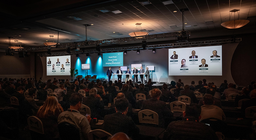
CTI SYMPOSIUM USA IS THE KEY MEETING POINT FOR GLOBAL FORWARD THINKERS IN AUTOMOTIVE POWERTRAIN DEVELOPMENT – FROM PASSENGER CARS TO HEAVY-DUTY VEHICLES.
Plenary Speakers and Panelists 2026
Micky BlySenior Vice President Propulsion Systems – Stellantis
Jordan ChobyGroup Vice President Powertrain Engineering – Toyota
Jon DarrowVice President of the North American Tech Center – Stellantis
Joe FadoolPresident & CEO – BorgWarner
Ramiro GutierrezPresident – ZF North America
Ingo ScholtenCTO – HORSE Powertrain
Paul ThomasPresident, Bosch in North America & President, Bosch Mobility – Americas
Luca ZampieriEngineering Director US – Neural Concept
The Expert Summit for a Sustainable Future Mobility
Only together we can create a sustainable future mobility. CO2 reduction is critical for automotive drivetrain. Here the battery electric drive using renewable energy is the focus. What can we do to increase efficiency and reliability, reduce cost and at the same time reduce the upstream CO2?
At CTI SYMPOSIUM the automotive industry discusses the challenges it faces and promising strategies. Latest solutions in the fields of electric drives, power electronics, battery systems, e-machines as well as the manufacturing of these components and supply chain improvements are presented. For the bigger picture market and consumer research results as well as infrastructure related topics supplement the exchange of expertise.
CTI SYMPOSIA drive the progress in individual and commercial automotive transportation. Manufacturer, suppliers and institutions are showing how to master the demanding challenges.
450+ INTERNATIONAL DELEGATES, EXHIBITORS & SPEAKERS
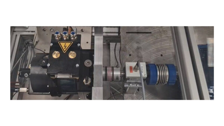
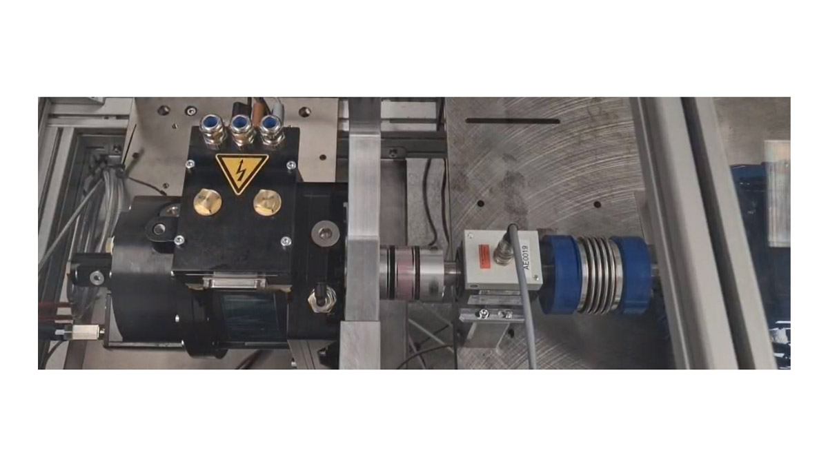
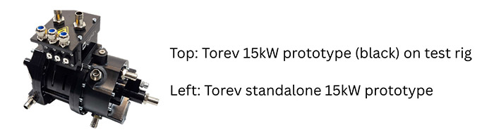
Torev Motors develops wound rotor axial flux motors for automotive and defense vehicles.
Building on proven, scalable technologies
Torev’s architecture builds on technologies already proven in production vehicles, including wound rotor motors used by companies including BMW and Nissan, and axial flux used by companies including Mercedes and Ferrari. By integrating these approaches, Torev aims to deliver motors capable of up to 2x the torque density of radial flux motors, that use 0 kg of permanent magnetic material, and that saves up to an estimated 50% on active material costs.
1.1 How it Works & Performance
Wound rotor motors, also called externally excited motors, replace permanent magnets with electrically excited coils. These motors offer greater torque and almost constant power at high speeds [1], wide efficiency maps stemming from direct control over the rotor fields, and material cost efficiencies from using no permanent magnets. Historically, these systems introduced greater weight, rotor thermal cooling requirements, and additional control complexity and cost stemming from the rotor energizing current, which modern designs are increasingly addressed through improved cooling strategies and power electronics. While brushed operation is traditionally the most common, modern brushes can last a vehicle’s lifetime and wireless power transfer methods are gaining in popularity.
Axial flux motors, also called pancake motors, take advantage of a shorter magnetic flux path that runs parallel to the axis of rotation, a cubic relationship between torque and motor diameter, and a greater magnetic interaction surface area to increase power and torque density along with efficiency [2]. This makes axial flux motors strong contenders for hybrid vehicle range extender and in-wheel drive applications. However, these very high-performance machines generally come with an equally high price tag arising from a combination of air gap control complexity in manufacturing, the use of materials like carbon fiber for structural integrity and lightweighting, and use of rare earth permanent magnets.
These architectures, when combined, enable Torev to develop magnetfree oil-cooled motors anticipated to produce peak torque and power densities of 15 Nm/kg and 3.5 kW/kg, and peak efficiencies upwards of 96% for their 180 kW 800 V flagship motor unit. These motors have an expected envelope of 370 mm OD x 225 mm Length.
This product is TRL 4 and has been tested and validated by 3rd party motor testing firms, with a 15kW sub-scale prototype in operation and the 180 kW units expected to be ready for customer validation testing in the next 12 months.
1.2 Applications & Opportunities
Key advantages of this technology include direct control over the rotor field windings, the use of no permanent magnets, and the axial flux architecture. The rotor field is directly controlled, enabling an additional degree of system-level powertrain design freedom, the ability to fully demagnetize the rotor fields, and full motor programmability suitable for software defined vehicle architectures. No permanent magnets means both cost savings and no thermal demagnetization risk, the peak temperature of the motor is instead defined by the insulation class. The axial flux geometry fits naturally into a hybrid vehicle’s bell housing and also enables direct drive optionality as these motors generally perform strongly at speeds matched to that of an ICE crankshaft.
References
[1] Schaeffler. Magnet-free axle drive EESM. https://www.schaeffler.de/en/products-and-solutions/e-mobility/magnet-free-axle-drive-eesm
[2] E-Mobility Engineering. (2021, May 17). Power and torque density. https://www.emobility-engineering.com/challenge-of-power-torque-density.
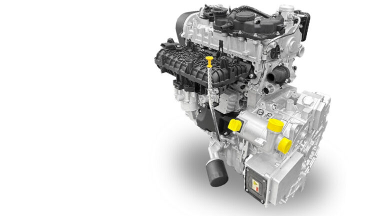
Dr. Cao Yang, Engineering Executive, Company: JJE Technologies Co.,Ltd The range extender, as a critical enabler for new energy vehicles, has long been challenged by the inherent trade-off between compactness, noise, vibration, and harshness (NVH), and system cost. This article presents JJE’s Integrated Active Cancellation Range Extender Technology, a next-generation system that fundamentally redefines the […]
Dr. Cao Yang, Engineering Executive, Company: JJE Technologies Co.,Ltd
The range extender, as a critical enabler for new energy vehicles, has long been challenged by the inherent trade-off between compactness, noise, vibration, and harshness (NVH), and system cost. This article presents JJE’s Integrated Active Cancellation Range Extender Technology, a next-generation system that fundamentally redefines the mechanical and control architecture of hybrid power units.
The technology is built upon three core innovations:
direct-coupled, oil-cooled coaxial architecture that eliminates the flywheel and all torsional damping elements;
an active torsional vibration cancellation strategy that generates an opposing torque wave relative to the generator torque profile to neutralize engine vibration;
a novel method for determining engine crankshaft position using the motor resolver signal without additional sensors.
Together, these innovations enable a system in which speed fluctuation is reduced by over 50% and body vibration by more than 85%, while achieving unprecedented mechanical simplicity and robustness validated in full-scale mass production. This paper details the design philosophy, implementation, and performance validation of the JJE range extender, establishing it as a benchmark for future integrated hybrid powertrains.
Introduction
Conventional range extenders inherit the complex architecture of traditional internal combustion engines, including flywheels, torsional dampers, and numerous sensors and communication networks, to manage noise and vibration. These components add weight, cost, and packaging complexity, while noise and vibration still compromise passenger comfort when the engine switches between operating points.
Moreover, delays inherent in conventional speed sensors and communication buses limit the effectiveness of vibration cancellation strategies, preventing precise tracking of the generator’s vibration waveform. After more than a decade of development, JJE has overcome these limitations by introducing a fully integrated range extender—a step-change innovation. The concept combines deep mechanical integration with intelligent active control. The result is a system in which the engine crankshaft, generator rotor, and oil pump rotor are rigidly connected along a common axis, allowing the generator to act as an active actuator that cancels vibration at its source—the internal combustion engine.
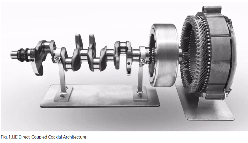
Direct-Coupled Coaxial Architecture
The first innovation is the system’s mechanical design: a rigid coaxial connection between the engine crankshaft, generator rotor, and oil pump rotor, without any flywheel or torsional damping elements (Fig. 1). In conventional designs, flywheels and torsional dampers are used to smooth engine torque before it reaches the generator. However, these components add rotational inertia, reduce dynamic response, increase axial length and system weight, and introduce wear-prone elements.
In JJE’s architecture, these components are intentionally eliminated. The crankshaft output flange is directly coupled to the motor shaft, with the oil pump rotor mounted at the rear. The entire rotating assembly behaves as a single rigid body with minimized moment of inertia. As a result, the system achieves a weight reduction of approximately 11 kg and a significant cost reduction. The removal of flywheel and damping elements introduces an NVH challenge: engine torque pulsations act directly on the generator rotor. This is addressed by the second innovation—the active control strategy.
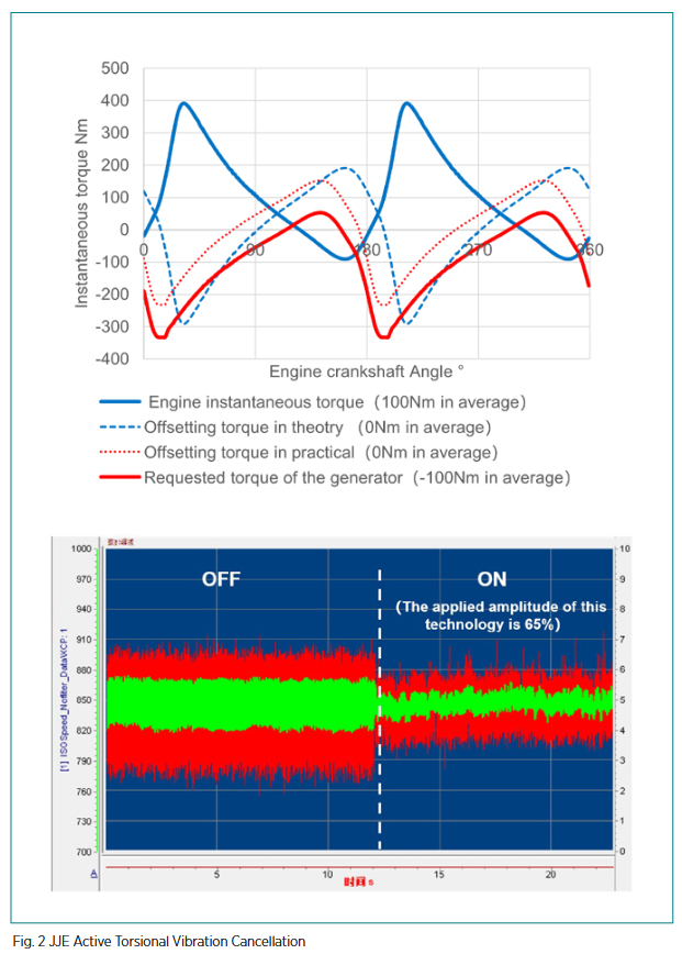
Active Torsional Vibration Cancellation (ATVC)
The rigid, low-inertia architecture is made feasible by the development of active torsional vibration cancellation (ATVC). The core concept is to treat the generator not only as an electrical load, but also as a torque actuator capable of producing a precisely controlled counteracting torque waveform.
JJE’s system implements an active control algorithm (Fig. 2). Using real-time crankshaft position data, the controller predicts the engine’s instantaneous torque contributions. Based on this prediction, an opposing torque waveform is synthesized and superimposed onto the generator output torque. This effectively creates a virtual torsional damper with zero mass and no mechanical wear.
The system reduces speed fluctuation by more than 50% compared to a passive damping solution. More importantly, vibration transmitted to the vehicle body is reduced by over 85%, delivering a substantial improvement in NVH performance.
Engine Crankshaft Position Detection via Motor Resolver
High-performance vibration cancellation depends on accurate, zerodelay measurement of crankshaft position. This innovation eliminates the need for conventional engine position sensors entirely. In JJE’s system, the motor rotor is rigidly coupled to the engine crankshaft, meaning both rotate at the same speed. The motor resolver inherently provides precise rotor angular position, which directly corresponds to the crankshaft position.
A dedicated method was developed to derive crankshaft position from the resolver’s raw sine and cosine signals at high refresh rates within the generator controller. During the first engine cycle after start-up, a calibration algorithm identifies piston positions by analyzing resolver signals in combination with the known engine firing order. Once synchronized, the resolver-derived angle is distributed within the controller with effectively zero delay, meeting the stringent requirements of the cancellation algorithm.
This approach eliminates the need for crankshaft position sensors, associated wiring, connectors, and signal conditioning circuits, improving system robustness while reducing cost and complexity. The solution has been fully validated in mass production.
System Integration and Production Validation
This system has been deployed in multiple mass-production vehicles, including the Beijing Auto BJ40E and BJ60E. Notably, the BJ40E has become one of the best-selling off-road SUVs in the Chinese market since its launch in April 2025.
Conclusions
JJE’s Integrated Active Cancellation Range Extender Technology represents a significant breakthrough in range extender design. By combining a directconnected architecture, active torsional vibration cancellation, and sensorless crankshaft position detection, JJE has created a system that is mechanically simpler, more compact, and substantially superior in NVH performance compared to conventional solutions.
With robustness proven in mass production, this integrated system is well positioned to enable the next generation of quiet, efficient, and cost-effective hybrid and range-extended vehicles.
Dr. Reik Laubenstein, Engineer, IAV Automotive Engineering Inc. Dr. Johannes Werfel, Team Manager, IAV GmbH Batteries are the core component of electrified vehicles. However, conventional approaches, that heavily rely on physical prototyping and extensive testing, are too slow and costly for the pace that is demanded by the market. IAV implemented virtualdriven processes with smart […]
Dr. Reik Laubenstein, Engineer, IAV Automotive Engineering Inc. Dr. Johannes Werfel, Team Manager, IAV GmbH
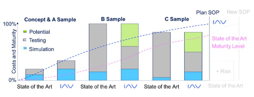
Batteries are the core component of electrified vehicles. However, conventional approaches, that heavily rely on physical prototyping and extensive testing, are too slow and costly for the pace that is demanded by the market. IAV implemented virtualdriven processes with smart testing achieving development time and cost reductions of up to 30 %.
Methodology
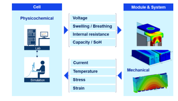
Often the development of EV batteries heavily relies on continuous and frequent hardware updates and extensive durability testing that proves challenging considering timelines and associated costs. Main obstacles are scarce component availability (e.g., cells) in early stages, and expensive & time-consuming testing loops. Shifting towards virtual development can mitigate these challenges, but these methods often fall short on capturing the complex interactions between the different domains (design, thermal management, function). However, IAV developed a project-proven methodology that focuses on early application of predictive component models, which can be coupled and used to predict the behavior of the higher-level system with complex interactions (e.g., module or pack, see Fig. 1) und thus, reduce expensive prototyping and testing during. The foundation of this “shift-left” approach are electro-physico-chemical models (EPCM) that describe the electrical, thermal and mechanical behavior of the cell. Due to the scarcity of physical cells at early stages of development, our internal tools and workflows enable deriving theoretical cell design parameters with minimal input to construct baseline cell models, that are continuously optimized with further progress. To further increase efficiency, we established a smart testing approach based on reinforcement learning to characterize cells in early stages, by utilizing neural networks to balance the testing effort and model accuracy. It has been shown that 60% of all relevant operational points can be sufficient to reach a comparable accuracy of a model that utilizes all measurement points of the measurement matrix. Once established, the EPCM can be seamlessly integrated into the aforementioned domains to enable further development and optimizations by the respective domain experts. This is realized via the versatile virtual battery testbench (VBT) framework developed by IAV and allows for model-in-the-loop (MiL) investigations in various other established toolchains, which are being utilized by various domain experts throughout the whole V-process (e.g., thermal management, BMS function development, exploration of mechanical constraints) and without requiring physical cell samples.
Figure 1
Application
A critical aspect in battery systems development is the ability to accurately understand and predict battery aging under realistic operating scenarios. In our approach the EPCMs are capturing structural changes on particle level (e.g., Li plating, SEI growth, particle cracking) in response to the change of the boundary conditions of the system via interaction through the VBT. This was applied in a representative project: failures in battery modules were detected at roughly half the targeted lifetime. A simulation-driven approach utilizing the cell model, completed within six weeks identified critical pressure accumulation caused by the interaction of cell aging, swelling, and module boundary conditions. Early virtual integration is estimated to have saved more than six months of testing and prototyping.