News


News from cti-symposium.world

Range anxiety is history! Get up to speed here on the hottest topics in electric powertrains
Ranges of over 600 km, ultra-high-speed charging … recent BEVs have long since proven how practical they are – and tomorrow’s models will go further still. To solve today’s pres-sing challenges, manufacturers need three things: expertise, innovative technologies, and courage.
Continue reading
Range anxiety is history! Get up to speed here on the hottest topics in electric powertrains
Ranges of over 600 km, ultra-high-speed charging … recent BEVs have long since proven how practical they are – and tomorrow’s models will go further still. To solve today’s pres-sing challenges, manufacturers need three things: expertise, innovative technologies, and courage.
CTI Symposium Germany 2025: see for yourself how e-mobility is progressing!
Fourteen deep-dive sessions with over 80 expert presentations await you in Berlin. Two deep-dive sessions are dedicated entirely to the latest developments in powertrains. How much potential do axial flux motors, range-extender drives and high-speed motors have? Will powertrains soon be a magnet-free zone? What’s the most compelling alternative to the permanent magnet synchronous motors that still prevail today? Find out more about our fascinating symposium program below.
Manufacturers present their highlights: From range extender solutions to long-haul trucks
The new Nissan LEAF: What makes the 3rd generation of this bestseller so convincing?
When Nissan launched the LEAF in 2010, it was the world’s first mass-produced electric vehicle. Up until late 2019, it was also the world’s best-selling BEV. In June 2025, the com-pany unveiled its third-generation LEAF. In Berlin, Shunsuke Shigemoto (Nissan) will describe the new model’s key innovations. These include a new battery system, a compact integrated drive unit, and a bidirectional onboard charger. A ‘big module’ increases the battery’s capacity density and charging performance. The integrated 3-in-1 drive unit com-bines the inverter, motor, and transmission in a single housing, for improved rigidity and a compact package. Benefits include improved NVH performance with unprecedented smoothness, and higher efficiency for greater range. The new model ships with a new bidi-rectional onboard charger as standard – ideal for charging e-bikes or powering tools. In fu-ture, the LEAF will also permit vehicle-to-grid backfeeding.
The electric axle of the Mercedes-Benz eActros600. Find out what powers the International Truck of the Year 2025.
After Bertram Wunderlich (Daimler Truck)’s presentation, you’ll know exactly why the eAcross600 deserves its Truck of the Year Award. Having already developed an e-axle for heavy-duty distribution traffic, Daimler Truck is now expanding its portfolio with an e-axle for long-haul applications. This is one of the next steps towards emission-free freight transport and the decarbonization of the industry.
In part one of his presentation, Bertram Wunderlich will explain the concept and design of the new eAxle. He will offer insights into possible concepts and their advantages and disadvantages, and will explore ideas for increasing efficiency. Part two will examine the technical implementation, the main components, and their respective functions. Starting with the inverter, the speaker will cover the entire eDrive train, including the motor, housing, transmission, axle, and cooling system. Finally, he will discuss the application of the unit in the vehicle, and the challenges it faces in a global vehicle portfolio.
Li Auto’s new Range Extender Powertrain – the next chapter in a successful story
Li Auto is a highly successful specialist manufacturer of REEVs (Range Extender Electric Vehicles) in the Chinese market. In Berlin, Dr. Qiang Liu (Li Auto) will describe the sys-tem architecture and key technologies of his company’s 3rd-generation range extender powertrain. His presentation will illustrate Li Auto’s systematic vehicle-to-chip technical ap-proach, which began by deriving system performance requirements and boundary condi-tions from the vehicle performance. On the component level, the speaker will explain how the electrical magnetic design of the PSM motor enhances generator efficiency, and will describe the key technologies of a high power density ASM traction motor. Dr. Qiang Liu will also cover solutions for power electronics and semiconductor technology (including the software structure) in detail, right down to the size and number of high-voltage IGBT and diode chips. Finally, the speaker will discuss how the platform solution can be scaled and extended for use in different vehicle segments.
Developers have a new favorite: electrically excited synchronous machines (EESMs), including high-speed brushless versions
The vast majority of EVs are still powered by permanent magnet synchronous motors (PMSMs). But driven by sustainability concerns and supply chain risks, the call for magnet-free electric motors is growing louder, and electrically excited synchronous machines (EESMs) could be the solution. Either way, high-speed motors are definitely trending.
The study presented by Brice Lecole (Valeo) will examine the significant system-level benefits of a high-speed e-axle architecture for EVs. The focus rests on ‘upspeeding’, which boosts power density via higher rpm at lower torque. Using advanced electric motor technology, a high-speed carbon-clad rotor was integrated into a standard two-step high-
ratio reduction gearbox. An optimal top speed of 22 – 25k RPM was determined for the tar-geted power range. As the study results show, higher motor speeds offer significant poten-tial for downsizing the electric motor. This in turn can reduce material consumption, motor manufacturing costs, and the overall mass of the e-axle.
In Berlin, Martin Burgbacher (AAM) will go one step further with a solution that involves motor speeds of 30,000 rpm. Together with a highly integrated propulsion inverter, this can substantially increase the power density of the motor and inverter to over 25 kW/liter. These targets were envisioned for a 650Vdc EDU application rated at over 200kW for both primary and secondary drive applications. As the speaker will explain, the 30k RPM motor cuts design costs by reducing the amount of copper and magnetic lamination materials re-quired. The stator is encapsulated with a thermally conductive plastic material, while the high-speed rotor was designed using copper bars for high efficiency. The transmission u-ses a high reduction ratio of 23:1, which translates to 4500Nm of torque at the axle. A highly integrated 650Vdc ring inverter is tightly integrated into the inner diameter of the stator end turns, and provides a max phase current of 350Arms.
Valeo and MAHLE have joined forces to develop an innovative, magnet-free electric axle system for high-end EVs with peak power ranging from 220 kW to 350 kW. As Camelia Jivan (Valeo) and Thomas Hennings (Mahle) will explain, the aim of this cutting-edge technology is to revolutionize the performance and efficiency of magnet-free electric mo-tors (EESMs). The project combines Valeo’s expertise in electric motors, high-efficiency inverters (SiC and switching cell technologies) and associated motor control with MAHLE’s expertise in magnet-free rotors and its MAHLE Contactless Transmitter (MCT) technology. In tests, the fully integrated brushless motors demonstrated efficiency levels of >96%, con-tinuous peak power in excess of 60%, and a 40% smaller carbon footprint than PMSMs of the same power. In their presentation, the speakers will describe the key design decisions, compare brushless and brush motors, and emphasise that brushless motors are the main alternative to PMSM.
Axial flux machines: more than just a niche product?
Radial flux motors are inherently more efficient than their axial flux counterparts, but may need higher gear ratios to deliver the same amount of torque to the axle. Axial flux ma-chines promise high power density – but does that still apply in combination with a trans-mission? In Berlin, Kristoffer Nilsson (Alvier Mechatronics) will offer a comprehensive comparison of axial and radial flux topologies. His simulation study compares two axial flux machines with two radial flux machines, across two types of transmissions: a standard two-layshaft design, and a coaxial planetary design. The study evaluates these combina-tions over standard WLTC driving cycles, as well as for acceleration capability, on two dif-ferent vehicle specifications. How did the candidates fare, and what conclusions can we draw? In Berlin, Kristoffer Nilsson will reveal all this and more.
Electrically excited synchronous motors (EESMs) are a promising alternative to permanent magnet synchronous motors (PMSMs), whose downsides include supply chain risks, costs, and sustainability. In Berlin, Dr. Philippe Farah (Yeesma) will show how the ad-vantages of EESMs can be perfectly combined with those of axial motors. YEESMA is cur-rently developing an innovative Electrically Excited Axial Flux solution. The dual rotor, sin-gle stator approach helps solve packaging and performance challenges by delivering up to 20% more torque volumetric density, cost savings of over 50%, and a 60% higher sustain-ability index score. Dr. Philippe Farah will also describe how novel manufacturing solutions are helping Yeesma to reduce the challenges of assembling axial flux motors. The inverter phase current has also been significantly reduced, contributing to the 50% cost savings described above. The presentation will examine applications ranging from 10 kW to 350 kW in detail.
CTI Symposium Berlin: Book now for this ultra-high performance density event!
Come and join us on December 2nd and 3rd, 2025, when decision-makers and experts provide cutting-edge insights into the topics that are driving the industry. Choose your per-sonal highlights from a top-notch program featuring 14 deep-dive sessions and over 80 lectures, as well as plenary sessions and discussions. Get talking to exhibitors at the CTI EXPO, and to young innovators in the Startup Area. Then in the evening, make invaluable new contacts in the relaxing atmosphere of our CTI Networking Night.
Welcome to Berlin!
Further Development of the Limestone Engineering Continuously Variable Transmission (CVT)
James Kalkstein, PE, Chief Engineering Officer and Principal, Limestone Engineering Services, LLC Limestone Engineering Services, LLC (LES) Limestone Engineering Services, LLC (LES) has continued development of our unique and patented CVT under patent #11,371,592. The development has moved from the Research Proof-of-Concept Prototype as shown in the patent disclosure to an engineered Development Prototype (DP#1) […]
Continue reading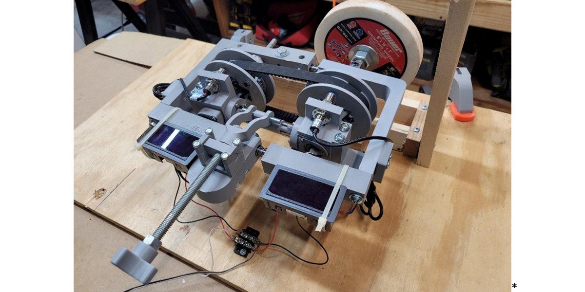
Further Development of the Limestone Engineering Continuously Variable Transmission (CVT)
James Kalkstein, PE, Chief Engineering Officer and Principal, Limestone Engineering Services, LLC
Limestone Engineering Services, LLC (LES)
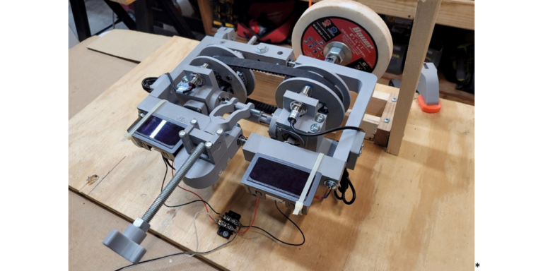
Limestone Engineering Services, LLC (LES) has continued development of our unique and patented CVT under patent #11,371,592. The development has moved from the Research Proof-of-Concept Prototype as shown in the patent disclosure to an engineered Development Prototype (DP#1) shown in the figure below (Figure#1).
*Figure #1: Development Prototype #1 (DP#1) on Test Bench Setup
The DP#1 is constructed from 3D-Printed Hyper-PLA material. This material is rated at a tensile strength that is approximately 20 % of the strength of typical aluminum. Therefore DP#1 has a limited torque capacity when compared to a full-production metallic unit. However, the belt is a production-ready 5Mx15mm cog-type timing belt with a torque capacity of approximately 95 N-M (70 lb-ft). The gear-ratio span for the DP#1 unit is setup to be from approximately 1.2:1 to 0.8:1.
The ratio-change actuator in the DP#1 uses a threaded rod to actuate the devices that changes the ratio. However, the patent includes actuation devices of any kind, including but not limited to; 1) electromechanical; 2) hydraulic, or 3) pneumatic.
Please note that:
1. Virtually any timing belt width and pitch is possible allowing for virtually any torque capacity and;
2. Ratio spans are a function of the physical size of the unit and can be increased or reduced by design.
Several design iterations have been made for the idler pulley arrangements. All proved to be satisfactory, and the final choice should be based on the final design chosen.
Testing:
This DP#1 has been tested on a test bench using a simple Prony-Brake absorber system. The test-applied torque/speed capacity is approximately 20 N-M (15 lb-ft) maximum at approximately 1,000 rpm. Please note that this is using non-metallic Hyper-PLA material and not aluminum or other metallic material components. Additionally, the input drive device was limited to these values (20 N-M (15 lb-ft) @ 1,000 rpm). We believe that this testing level was very close to the ultimate-strength of the component design using this Hyper-PLA material. However, a material change (e.g … to aluminum or steel) should bring the capability to the level of the belt ultimate-strength without any additional design changes.
Cost and Supply Chain:
The supply chain for the DP#1 requires no special components for belts, fasteners, or bearings (rotational, thrust and linear). They are all Commercial Off-The-Shelf (COTS) items. However, the main operating components are specially designed for this application. We have investigated small batch fabrication for a small number (~ 5 units) of DP#1 for full-power test-bench testing. We estimate that these units would cost approximately $500 − $750 per unit to produce, not including assembly labor and special assembly fixtures. We estimate that in series-production, the cost would fall by, at a minimum, one order of magnitude , but could have even greater reductions in larger volumes.
Revolutionizing Electric Mobility with Emil Motors’ SAM Technology
Maximilian Guettinger, CEO & Co-Founder, Emil Motors The electric vehicle (EV) industry is experiencing unprecedented growth, driven by global demand for sustainable transportation. Yet, this momentum faces hurdles: the reliance on rare-earth magnets − primarily sourced from China − introduces supply chain risks, compounded by potential tariffs that could disrupt production and escalate costs. Amid […]
Continue reading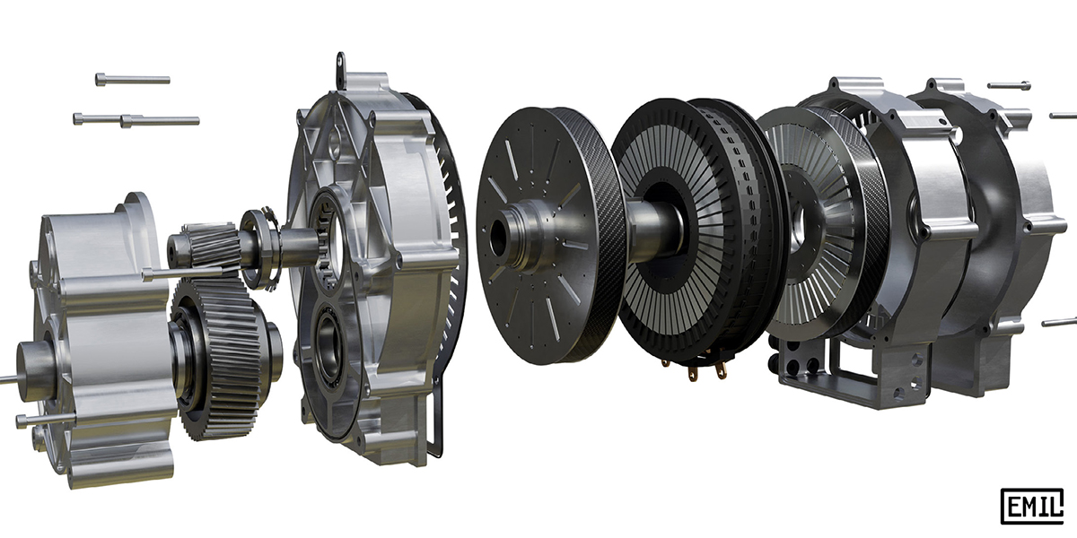
Revolutionizing Electric Mobility with Emil Motors’ SAM Technology
Maximilian Guettinger, CEO & Co-Founder, Emil Motors
The electric vehicle (EV) industry is experiencing unprecedented growth, driven by global demand for sustainable transportation. Yet, this momentum faces hurdles: the reliance on rare-earth magnets − primarily sourced from China − introduces supply chain risks, compounded by potential tariffs that could disrupt production and escalate costs. Amid these challenges, Emil Motors emerges as a game-changer with its Segmented Axial Flux Asynchronous Motor (SAM) technology. This magnet-free innovation not only sidesteps geopolitical and environmental concerns but also delivers superior performance, efficiency, and scalability, positioning it as a cornerstone for the future of electric mobility.
The standard induction motor and its shortcomings
Induction Motors (or asynchronous motors) are well known work horses in industrial applications and even in automotive drivetrains. They work well and do not rely on magnets. In principle an induction motor replaces the magnets inside the rotor with conductive bars. In operation the stator field rotates faster than the rotor, which induces currents in the rotor conductors. These currents then create the rotor field which interacts with the stator to produce torque. Sounds easy enough, so why are we not using them everywhere?
The issue is low power density coupled with high manufacturing expenses for high efficiency induction motors. Torque density in induction motors is much lower compared to permanent magnet designs and if you want to build them cheaply you will sacrifice efficiency. The difficult bit is the manufacturing of the rotor conductor. For a standard radial flux machine, it must be cast or assembled in a complicated welding or brazing process. The cheapest way is cast aluminum, which has lower conductivity compared to copper and results in higher losses and lower efficiency. Achieving high efficiency in a conventional induction motor requires copper rotor conductors. These can be cast with expensive molds, or they can be assembled using a costly brazing process. When going through this complicated process you will still end up with a machine that will be much heavier or less powerful than a permanent magnet motor, making it undesirable.
Emil’s mission was clear. Make induction motors more powerful with low weight and low manufacturing cost. Achieving Performance without magnets.
Unveiling the SAM Architecture
SAM’s brilliance lies in its axial flux design, a departure from the conventional radial flux motors dominating the market. Unlike radial designs, where magnetic flux flows perpendicular to the rotor shaft, the Emil’s disc-shaped configuration directs flux parallel to the shaft. This allows for a larger rotor radius within a compact footprint, boosting torque density and power output without increasing the motor’s size. The result is a lightweight, high-performance motor that punches above its weight class.
The stator is a core component towards achieving extraordinary performance. Segmented into precise sections, it achieves a slot fill factor exceeding 65 % which describes how much of the available space is filled with copper wire, maximizing space efficiency for enhanced performance.
Our fully automated winding process is exceptionally well suited for mass production – a critical advantage for scaling EV manufacturing. Conventional round wire windings achieve slot fill factors around 40 %. State of the art hairpin designs may reach 60 % but require very difficult laser welding processes or huge machines for a continuous wave winding.
Compared to this we can easily wind a coil segment by segment and use reliable well known welding processes. A similar approach was pioneered in the world of smaller electric motors in hybrid vehicles, where it has already proven itself to be cost efficient.
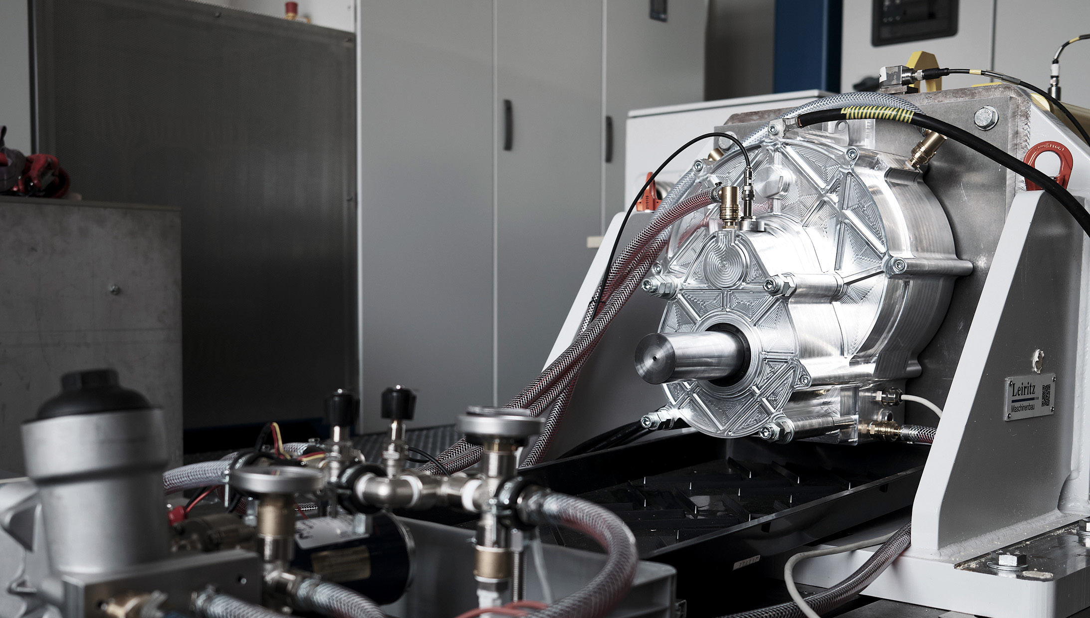
Meanwhile, SAM’s integrated oil cooling system sets it apart. Oil flows through channels in direct contact with the copper windings, minimizing thermal resistance and maintaining optimal performance even under high loads.
Cooling the rotor conductors is equally important in an induction motor. SAM achieves this feat by integrating cooling channels near the rotor conductors, keeping continuous power up and losses down.
Both of these revolutionary technologies, winding and integrated oil cooling are made possible using advanced plastics. Injection molding is much more manageable on small stator segments and creates advanced geometric features without increasing cost at all.
Together with our manufacturing partner Schlaeger we have developed an advanced injection molded segment design including very thin walls for slot insulation. No need for slot liners. Oil cooling channels, structural support and winding ixation all taken care of with a simple and cheap injection molding process. The best part is no part, the best process is no process.
The rotor construction is equally impressive, diverging from conventional manufacturing technology. Emil’s axial flux topology allows for major changes and innovation inside the rotor. For example, we can incorporate significant structural reinforcements on the outside of the rotor for high rotor speeds, which is much harder to achieve in a standard radial flux machine.
Manufacturing and assembly of the rotor conductor is simplified, no casting or welding is necessary. This enables the usage of higher performance alloys and a simplified manufacturing process.
As previously explained a conventional induction motor requires copper conductors in the rotor to achieve great efficiency numbers. This is not the case for SAM. The axial flux topology enables big rotor slots with a high cross section. This decreases losses, even when using a material with lower conductivity like aluminum. Additionally, the usage of different alloys makes it possible to achieve higher conductivity compared to cast alloys.
The SAM-M240 showcases these innovations:
- Peak Shaft Power: 330 kW
- Peak Torque: 450 Nm
- Max Speed: 16,000 RPM
- Efficiency: >97 %
- Active Weight: 35 kg (electromagnetic components only)
At just 35 kg of active weight, the SAM-M240 achieves a power-to-weight ratio that rivals permanent magnet motors, proving that magnet-free designs can lead the pack.
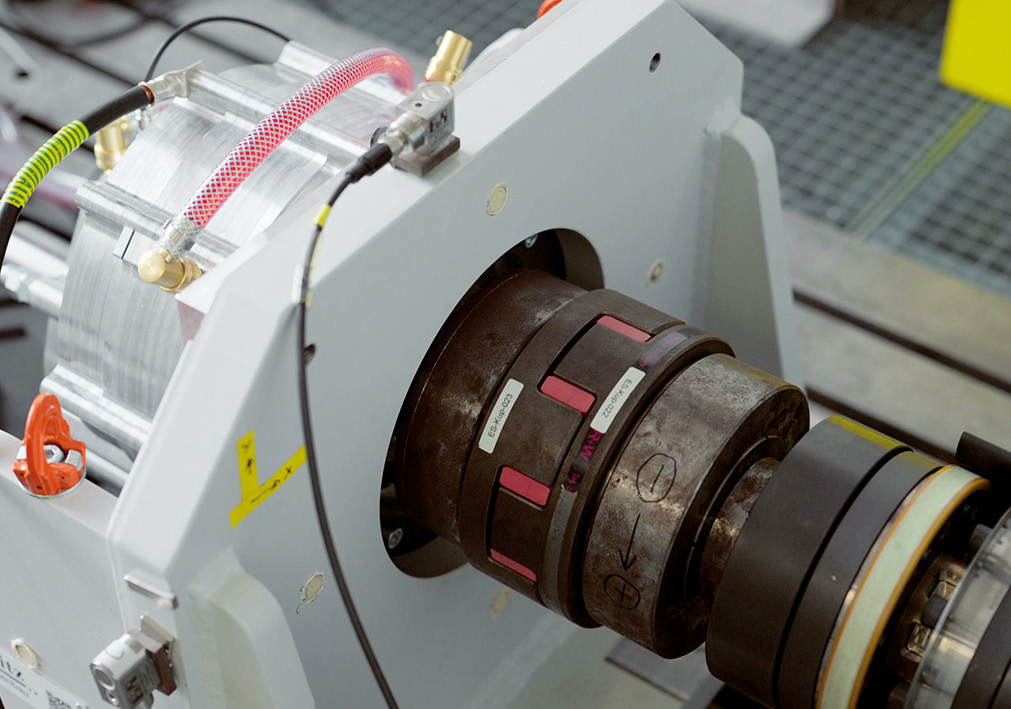
These performance claims have been validated through hours of testing data on a test bench. Talk to us directly to get more information on testing and validation of this groundbreaking technology.
A Competitive Edge Over EESM
To appreciate Emil’s significance, consider its magnet-free competitors, such as the Externally Excited Synchronous Machines (EESM) from BMW, ZF and Mahle. EESM technology replaces rare-earth Magnets with an electrically energized rotor, using current to generate the magnetic field. While effective, this approach requires additional power electronics to manage rotor excitation, increasing complexity, weight, and cost. These extra components can also introduce reliability concerns over time, a drawback in high-stakes EV applications.
In contrast, SAM relies on induction motor principles, eliminating the need for rotor excitation systems. By inducing a magnetic field through the stator’s interaction with aluminum conductors in a dual rotor setup, Emil achieves simplicity without sacrificing performance. Its axial flux design delivers torque density on par with permanent magnet motors, while its lightweight construction − just 35 kg of active mass − outshines EESM’s bulkier profile. The motor’s ability to hit 16,000 RPM enables high power capability and low motor weight.
In addition to the increased power density, Emil brings down cost by using an aluminum conductor in the rotor compared to expensive copper windings in EESM technology.
Efficiency is another win. With over 97% efficiency, SAM minimizes energy losses, extending vehicle range − a priority for manufacturers and consumers alike. Compared to EESM, SAM offers a streamlined design, higher power density, and lower production costs, making it a standout choice among magnetfree solutions. It strikes an unrivaled balance of performance, efficiency, and affordability, ready to meet the demands of mass-market EV production.
Strategic Resilience and Sustainability
Emil’s advantages extend beyond the technical. By using widely available materials like copper and aluminum, it eliminates dependence on rare-earth magnets, shielding manufacturers from supply chain volatility. To this day 90% of rare earth magnet production is controlled by China and magnet motors rely on that 100%.
Getting rid of these critical materials in your motor design is the fastest and easiest way to protect against these risks.
We have seen how quickly tariffs can get out of hand and the rare earth supply chain will take a very long time to build up in other countries than China.
For EV manufacturers, this translates to a competitive edge. Emil enables the production of high-efficiency, cost-effective vehicles without the risks tied to magnet-based motors. Its readiness for automated, large-scale manufacturing will accelerate adoption, empowering the industry to meet rising demand without compromise.
Driving the Future Forward
Emil Motors’ SAM technology is more than an engineering breakthrough − it’s a vision for a resilient, sustainable EV ecosystem. With its lightweight design, exceptional efficiency, and magnet-free architecture, SAM redefines what’s possible in electric propulsion. It challenges the status quo, proving that innovation can overcome the limitations of traditional motor technologies.
We invite industry leaders, engineers, and visionaries to experience this revolution firsthand. Visit Emil Motors to explore how we can power your next EV project, enhance your competitive edge, and contribute to a cleaner, more sustainable future. Together, let’s drive electric mobility into a bold new era.

Multi-Speed Transmission with Uninterrupted Shifting for EV & IVT for HEV
Raja Rajendran MSME, President, EcoNovaTech LLC Prashanth Rajendran MSME, PhD Candidate, CEO, EcoNovaTech LLC Breakthrough innovation using Geneva mechanism for transmissions Multi-speed uninterrupted shifting for EV IVT with uniform input-to-output ratio, NOT dependent on friction for HEV For the last several years, EcoNovaTech has been developing multiple innovative technologies to solve problems that are in […]
Continue reading
Multi-Speed Transmission with Uninterrupted Shifting for EV & IVT for HEV
Raja Rajendran MSME, President, EcoNovaTech LLC
Prashanth Rajendran MSME, PhD Candidate, CEO, EcoNovaTech LLC
- Breakthrough innovation using Geneva mechanism for transmissions
- Multi-speed uninterrupted shifting for EV
- IVT with uniform input-to-output ratio, NOT dependent on friction for HEV
For the last several years, EcoNovaTech has been developing multiple innovative technologies to solve problems that are in the forefront of the automotive industry. With its latest developments, EcoNovaTech provides a paradigm shift in transmission technology with uninterrupted shifting and ALL gear-based transmission.
Multi-Speed Transmission with Uninterrupted Shifting (MSTUS) for EV:
OEMs are continually striving to increase the range per charge for EVs. Some OEMs now recommend not depleting the battery below 25 % capacity, to extend its life. Battery charges relatively fast for the first 80 % but the last 20 % takes about as much time. Therefore, charging the battery up to 100 % could take overnight. However, there are concerns that the battery can catch fire making it difficult for consumers to use the full capacity. Moreover, battery degrades depending on the frequency and number of times it is charged and discharged. A transmission that can improve the range will reduce this frequency thereby extending battery life. So, OEMs are actively looking for a multi-speed transmission in place of a single speed Transmission to increase the range.
OEMs currently use two stage reduction for EVs. They are also actively looking into two speed transmissions with two stage reduction. Ideally, shifting occurs at around 40 − 45 miles per hour at which the wheel spins at about 650 − 750 RPM and the motor spins at about 6,500 − 7,500 RPM, since two stage reduction results in about one tenth the RPM of the electric motor. Current technology takes about 150 milliseconds of interruption for synchronizing and shifting, which causes a delay in achieving 0 − 60. So, a Multi-Speed Transmission with Uninterrupted Shifting (MSTUS) is desirable since it further increases the range, without affecting the time needed for 0 − 60. For electric motors spinning at 7,000 RPM the first reduction results in about 2,200 − 2300 RPM. This allows about 25 − 30 milliseconds for the transmission to shift over a full revolution, during the second reduction.
Smooth shifting occurs when the vehicle speed remains constant during shifting. Since vehicle speed is a product of motor RPM and angular velocity ratio, the change in this ratio should be inversely proportional to the change in motor RPM. Since the rotor of an electric motor has very low inertia when compared to IC engines, the RPM can be rapidly changed without changing the vehicle speed during shifting. As a result, occupants will not experience a jolt during shifting.
Experimental study using chain and sprocket mechanism for uninterrupted shifting shows that when shifting in about 19 milliseconds, most occupants may not experience the abrupt change in vehicle speed. However, use of chain and sprocket mechanism in transmissions is still in developmental stage. Noise and durability issues must be overcome. Chain and sprocket mechanism is not commonly used in transmissions in the industry.
Founded in 2014, EcoNovaTech has been dedicated to its mission of designing custom eco-friendly products through simple, effective engineering solutions and being a leader in Automotive Engineering.
In 2021, EcoNovaTech came up with a break through invention for Multi-Speed Transmission with Uninterrupted Shifting where the motor is continuously powering the wheels, even during shifting. It replaces the synchronizer with custom Geneva mechanism where the Geneva pin wheel has multiple pins and the Geneva slot wheel has multiple custom slots, along with dog clutch. The force required to operate a dog clutch is negligible.
With its latest innovation, EcoNovaTech now has two MSTUS solutions (one using non-circular gears and the other using Geneva mechanism) for EVs that are patent pending in multiple countries.
To briefly explain the operating principles of this innovation, both EcoNovaTech solutions use a transition module for uninterrupted shifting. The transition module transmits power parallel to the transmission gears in the transmission. The transition module can be engaged or disengaged using a dog clutch. The transition module has non-circular gears or Geneva pin and slot wheels cycling smoothly through all the constant angular velocity ratios used in the transmission, ramping up and down as needed. In a two-speed transmission, the transition module has 4 zones, a constant low speed zone, ramp up zone, constant high-speed zone, and a ramp down zone. Thus, it alternates between two constant speed zones sandwiched by a ramp up zone and a ramp down zone.
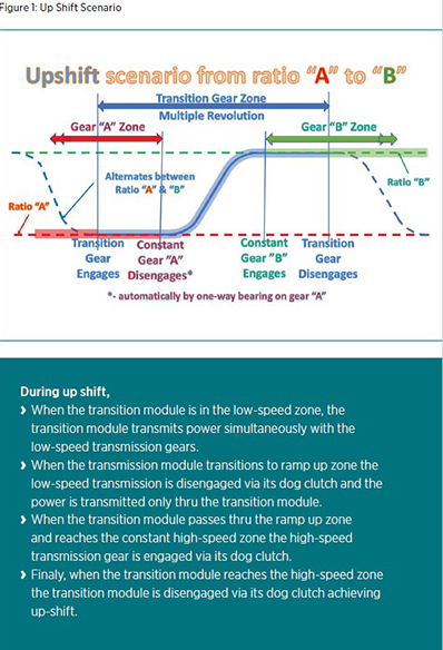
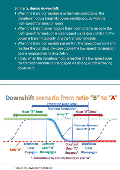
Use of partial gears for the constant zone makes it economical and less complex, and the number of pins can be reduced to 1 pin for up-shift and 1 pin for down-shift.
Use of helical gears reduces the space required when compared to chain and sprocket with tensioner. Also, helical gears provide a smoother and quieter ride at higher efficiency, when compared to chain and sprocket systems. A pair of Geneva wheels without partial gears and a pair of Geneva wheels with partial gears are shown in the figure.
Unlike in DCT the need for a high-pressure hydraulic system is eliminated resulting in significant savings. Also, the DCT only decreases the duration of interruption while EcoNovaTech innovation COMPLETELY eliminates the interruption. The lower ratio driven gear is placed on a one-way bearing on its shaft eliminating the need for linking it through a dog clutch. During reversing or regenerative breaking this must be connected through a dog clutch.
EcoNovaTech’s first solution is best suited for luxury passenger vehicles. For such vehicles, it is recommended that duration of uninterrupted shifting is extended when compared to current emerging technology, for a perfectly smooth ride. This solution uses a Duration Extender Module (DEM) that extends the duration of uninterrupted shifting to an optimal value of 30 − 50 ms (multiple revolutions) with zero interruption. DEM uses additionally a pair of overdrive gears., however is highly suitable for luxury passenger vehicles.
EcoNovaTech’s second and latest solution uses a DEM and eliminates the shortcomings of the chain and sprocket solution that is currently being developed in the industry. In 2019, EcoNovaTech developed a solution for uninterrupted shifting without a DEM using non-circular gears (patent pending). EcoNovaTech now has a less expensive innovative design (patent pending) that uses Geneva pin and slot mechanism with a customized slot, in lieu of non-circular gears, to transition from one angular velocity ratio to another. Geneva wheels can be mass produced at a lower cost when compared to non-circular gears.
Since the original design, EcoNovaTech has come up with a significant improvement where the Geneva wheel has only one pin for upshift and one pin for downshift, with the addition of two pairs of partial gears.
For EV, since the electric motor has a low inertia and can change the RPM instantaneously, shifting can occur within one revolution of the input from the electric motor. Since EV uses two stage reduction, it is advantageous to have the uninterrupted shifting happen in the second stage so that it spans a longer duration.
Non-friction dependent IVT for HEV:
In a hybrid vehicle, since we have a combination of IC engine and electric motor, a smaller IC engine can be used. An IVT can get maximum power out of a small engine for a quick acceleration.
EcoNovaTech has two innovative IVT solutions, one using non-circular gears (patented in US, China and Japan, and patent pending in Canada and India) and its latest using Geneva wheel mechanism (patent pending), along with other COTS components.
The operating principle involves converting
- uniform rotation from the engine to non-uniform rotation using non-circular gears or Geneva mechanism
- non-uniform rotation from above to linear oscillation (a portion being uniform) of a rack using a Scotch yoke mechanism
- linear oscillation of the rack to rocking motion of a pinion
- rocking motion of the pinion to a unidirectional uniform rotation of the output using a one-way bearing
The location of the pin in the scotch yoke mechanism dictates the angular velocity ratio. With as low as 3 scotch yoke modules, a continuous and steady output can be achieved.
The ratio changing mechanism in EcoNovaTech’s solution uses a unique and simple feature enabling the relocation of the crank pin in a rotating coordinate system from a fixed coordinate system. This is used to change the input-to-Output ratio for the transmission. The crank pin location can be changed purely mechanically at high RPMs so that it can be operated with a lever or cable. Planetary gears, computer controlled clutch or reversible one-way bearing can be used to achieve reverse gear. Use of reversible one-way bearing eliminates torque recirculation thereby reducing the peak load on the one-way bearing. This results in overall size reduction, since the size of the one-way bearing increases with the torque that is transmitted via the one way bearing.
Use of elliptical gears produce close results as non-circular gears, allowing ease of mass production since the driving and driven non-circular gears can be identical. EcoNovaTech’s latest IVT solution using Geneva wheel mechanism instead of non-circular gears will significantly reduce the manufacturing cost associated with non-circular gears.
EcoNovaTech’s eco-friendly innovative technical solutions can help OEMs progress towards the goal of Net-Zero Emissions by 2050 to help stop climate change.
Analysis of E-Motor Oil Cooling using Smoothed Particle Hydrodynamics (SPH)
Johannes Becker, Dive Engineering Software, Inc. Felix Pause, dive solutions GmbH Drivetrain electrification across the automotive and commercial vehicle industry drives increasingly power-dense electric motor designs, which require well-engineered cooling systems. Front-loading e-motor thermal simulations in the early design stage can de-risk prototypes and unlock more innovative designs.
Continue reading
Analysis of E-Motor Oil Cooling using Smoothed Particle Hydrodynamics (SPH)
Johannes Becker, Dive Engineering Software, Inc.
Felix Pause, dive solutions GmbH
Drivetrain electrification across the automotive and commercial vehicle industry drives increasingly power-dense electric motor designs, which require well-engineered cooling systems. Front-loading e-motor thermal simulations in the early design stage can de-risk prototypes and unlock more innovative designs.
The Role of Smoothed-Particle Hydrodynamics in Drivetrain Development
As the automotive industry is shifting towards electrification, the design of electric motors is key for optimizing vehicle performance. Balancing increased power and longevity with compactness and simplicity necessitates the use of sophisticated cooling strategies to maintain optimal operating temperatures. Various simulation methods have been explored in the past, ranging from traditional Volume of Fluid (VOF) techniques to particle-based approaches.
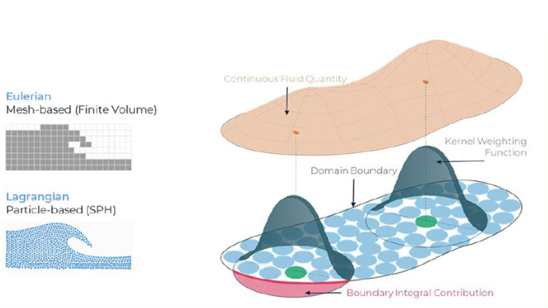
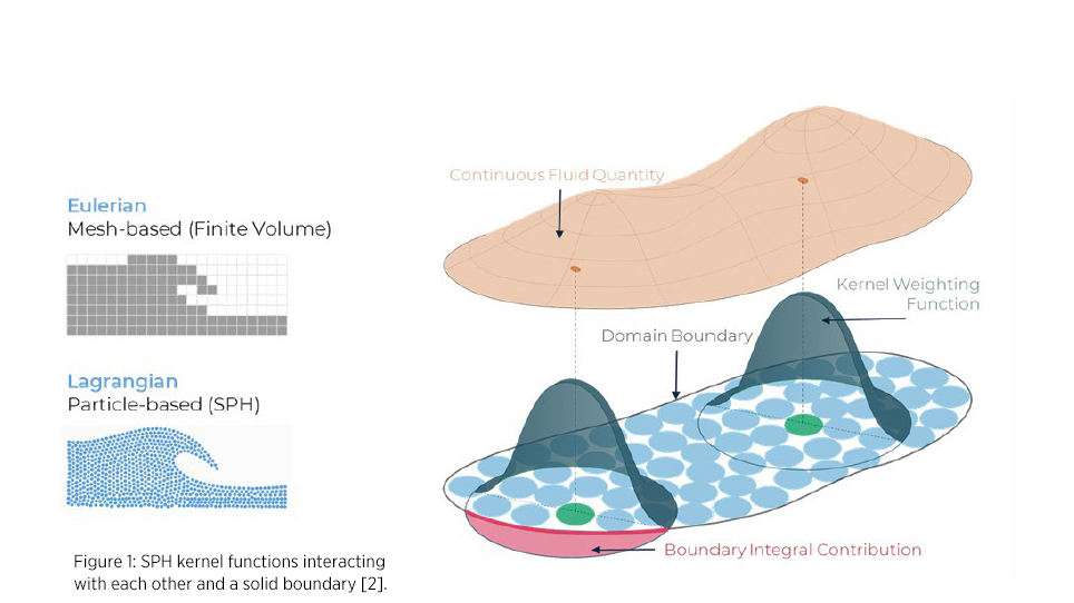
In response to increasing market pressure for faster, more efficient product development under constrained resources, Smoothed Particle Hydrodynamics (SPH) offers a flexible and powerful simulation approach, particularly suited for early-stage design. Unlike traditional CFD, SPH − as the name suggests − simulates fluids as a collection of small particles and does not require mesh generation (see Figure 1). This provides significant pre-processing and numerical efficiencies in cases where mesh generation and remeshing are a bottleneck in VOF methods, allowing engineers to explore large numbers of design variations quickly and cost-effectively. For that reason, SPH has become a widely used method of analyzing lubrication and cooling performance in drivetrain engineering, due to its ability to accurately model free surface and multiphase flows, as well as its efficacy in handling complex geometries and moving components. Consequently, SPH is increasingly applied in the design of electric motors as well.
Modeling Heat Transfer in Complex Geometries with SPH
Correctly predicting cooling performance in simulation fundamentally requires accurate modeling of surface wetting by the coolant, i.e. a good surface tension model, and consideration of the (often significant) temperature-sensitive viscosity of coolant oils [1]. SPH enables detailed simulation of how coolant oil absorbs and transfers heat across complex geometries like coil windings, accounting for temperature-dependent viscosity layers. By applying adaptive particle refinement [2] and realistic boundary conditions, SPH captures both transient and steady-state heat transfer behaviors. This allows engineers to evaluate heat transfer coefficients, optimize cooling strategies, and support thermal network models − especially in areas where empirical data is lacking.
This article presents findings from simulations of a simplified, actively cooled e-motor employing SPH. The results are validated against experimental data, demonstrating the method’s efficacy in predicting oil dynamics and heat transfer.
Experimental Reference and Simulation Setup
To validate the applicability of SPH in real-world designs, we examined an experimental e-motor cooling case by Davin et al. [3] as our reference scenario. Davin et al. investigated a 40kW radial flux machine equipped with 12 coils and examined different cooling configurations. Here, we focus on investigating a setup utilizing 5 inlets to distribute oil onto the coil windings. Since the experimental setup is symmetrical, our simulation model encompasses only half of the domain, with symmetry boundary conditions applied to the center plane. The setup is illustrated in Figure 2.
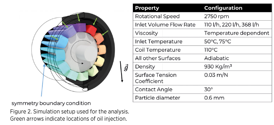
To validate the method against the experimental references, the inlet mass flows and inlet temperature of the coolant are varied. Since the properties of the coolant oil were not reported in the original work, some assumptions had to be made. As viscosity was given at 50 and 75°C, the following exponential law was used to interpolate between these two points and account for the influence of reduced viscosity with increasing temperature:
![]()
The density, thermal conductivity, specific heat capacity, surface tension coefficient and contact angles of the coolant used in the experimental work were not reported. Thus, typical values for coolant oils were applied (see Figure 2).
Results
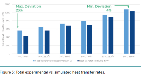
For each of the six operating points, the heat flow rates on the coils are obtained and compared with the experimental results. The simulation generally follows the experimental trend in [3] of increasing heat transfer rates with increasing volume flow rates and decreasing inlet temperatures. Moreover, a 77 % to 96 % match with experimental reference is found for the 6 operating points (see Figure 3). Given the accuracy of an experiment and the assumptions made, this indicates that the simulation can capture the complex multiphase flow present in the e-motor.
The method can therefore be used to test different design variations. In Figure 4, a snapshot of oil distribution predicted by the simulation is given. Here, the oil flow could be optimized by changing the nozzle position or design, ensuring that all coils are adequately cooled.
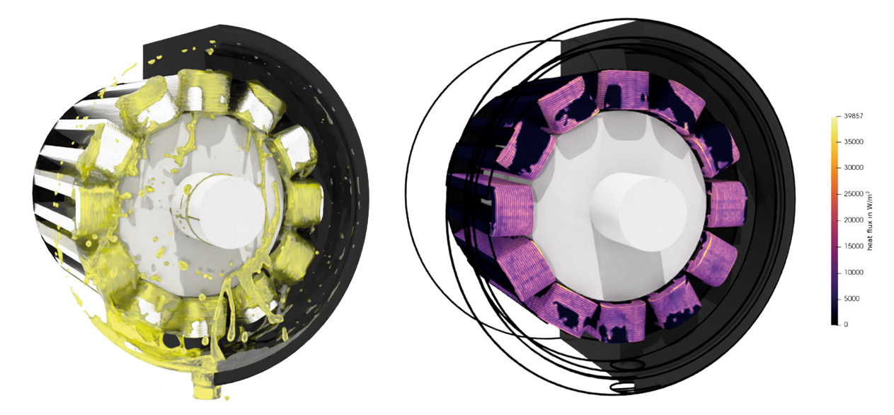
Figure 4: Oil distribution and heat flux at 368 l/h and 75°C.
Conclusions
The Smoothed-Particle Hydrodynamics method is widely applied and extensively validated in different sectors and applications. I can reliably predict complex multiphase flows in drivetrain, automotive, manufacturing, and more. Our results show accurately predicted heat transfer in the e-motor case, with deviations from experimental data ranging from 4 to 23 %.
Initial setup time was around 2 − 3 hours and only minutes for every additional operating point, the computational effort for each operating point was around 3 − 6 hours. By integrating SPH within a scalable, cloud-based platform, conducting extensive parametric studies, such as testing different nozzle types, orientations, placements, and coolant flow rates, can be parallelized. Automated DoE configuration and parallel execution of simulation and data analysis (i.e., simulating all operating points in parallel) allow for rapid design space exploration [4] − enabling engineers to investigate the effect of nozzle types, positions, inlet conditions (temperature/flow rate) or other design changes with same-day turnaround.
As the automotive industry accelerates toward more compact, powerdense electric drivetrains, SPH offers a critical simulation tool to meet thermal management challenges early in the design cycle − supporting faster innovation, reduced prototyping costs, and more robust e-motor designs.
Sources:
[1] G. A. Mensah, P. Sabrowski, and T. B. Wybranietz, “Practical guidelines on modelling electric engine cooling with SPH,” in 2023 International SPHERIC Workshop, 2023.[2] B. Legrady, “Particle-Based CFD Study of Lubrication in Power Transmission Systems Using Local Refinement Techniques,” Power Transmission Engineering,
vol. February 2024, 2024.
[3] T. Davin, J. Pellé, S. Harmand, and R. Yu, “Experimental study of oil cooling systems for electric motors,” Applied Thermal Engineering, vol. 75, pp. 1–13, 2015.
[4] B. Legrady, “Efficient Numerical Assessment of Thermal Effects in a Gearbox Using Smoothed Particle Hydrodynamics,” in American Gear Manufacturers Association,
in Fall Technical Meeting, vol. 24FTM25, 2024.
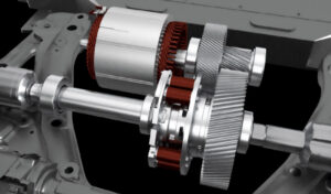
World’s First Disconnect and Locker Combo Differential (DL ComboTM)
JJE’s New Solution for High-Efficiency, High-Capability eAWD Dr. Yang Cao, Transmission Manager, JJE Technologies JJE Technologies proudly presents the DL Combo™, the industry’s first fully integrated disconnect and locker differential system. By combining eDisconnect and eLocker functionalities into a single, compact unit, this innovation provides electrified all-wheel-drive (eAWD) vehicles uncompromised off-road capability and low energy […]
Continue reading
World’s First Disconnect and Locker Combo Differential (DL ComboTM)
JJE’s New Solution for High-Efficiency, High-Capability eAWD
Dr. Yang Cao, Transmission Manager, JJE Technologies
JJE Technologies proudly presents the DL Combo™, the industry’s first fully integrated disconnect and locker differential system. By combining eDisconnect and eLocker functionalities into a single, compact unit, this innovation provides electrified all-wheel-drive (eAWD) vehicles uncompromised off-road capability and low energy consumption.
Introducing the DL Combo™ Differential
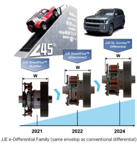
JJE launched its DirectFlux™ eLocker in 2021, now in use by several OEMs including in the newly introduced Beijing Automotive BJ60e and BJ40e extended-range off-road SUVs. This eLocker utilizes JJE’s unique electromagnetic clutch technology to lock up 6000 Nm of half-shaft torque within just 70 milliseconds.
JJE’s Disconnect & Locker Combo Differential, or DL ComboTM Differential
In 2022, JJE introduced the DirectFlux™ eDisconnect, offering both mono-stable and bi-stable configurations. This system enables real-time AWD/2WD switching at any vehicle speed, improving energy efficiency and electric range by 7–10 %.
Now, with an innovative, highly integrated mechanical design, JJE’s new DL Combo™ Differential merges these two systems into a compact differential with the same envelope as a conventional differential − making it fully interchangeable for OEM applications.
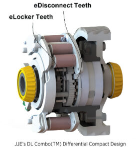
Compact. Capable. Integrated.
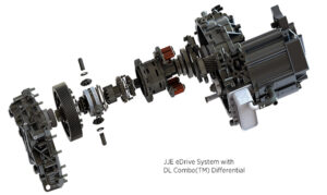
The DL Combo™ features a deeply integrated, nested mechanical structure that leverages JJE’s DirectFlux™ electromagnetic clutch configuration. As a result, the DL Combo™ differential maintains the same envelope as a conventional unit while offering dual functionality − eDisconnect and eLocker − within a single package.
Compared to standalone solutions, this design allows standard layout, significantly reducing the complexity and weight of the eDrive system with such dual functions. It allows vehicle OEMs to offer different drivetrain functions − conventional, disconnect only, locker only, or combined disconnect and locker − with standard mechanical interfaces.
JJE’s eDifferential Family & Roadmap
For OEMs, balancing efficiency against off-road and dynamic capabilities has long been a challenge. JJE’s DL Combo™, built upon its proven DirectFlux™ clutch technology, eliminates that offering below features:
- eDisconnect for 4×2 mode and drag loss reduction
- eLocker for 4×4 mode with 100 % torque transfer and maximum traction
Already validated in production vehicles, the DL Combo™ marks a major leap in electrified drivetrain systems.
Ideal for Secondary Axles
The DL Combo™ is especially suited for secondary drive axles − for instance, enabling a 4×4 off-road SUV to seamlessly switch to 4×2 for efficiency, while maintaining full locking capability when additional taction is needed.
Technical Breakthroughs
The DL Combo™ integrates two subsystems:
- eDisconnect: Electronically decouples the secondary axle in <70 milliseconds, reducing drag losses by up to 95 % and increasing electric range by 7 − 10 %
- eLocker: Delivers rigid locking between left and right half shafts for full torque transfer − even in extreme off-road scenarios
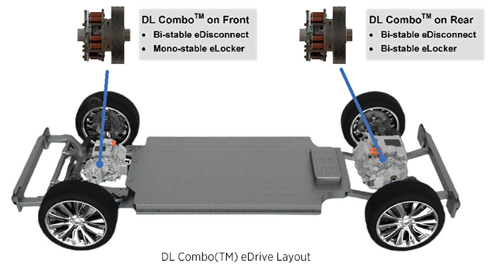
Both functions can be configured as bi-stable or mono-stable, depending on application needs. Two typical configurations meet different functional safety targets:
- Front axle: Bi-stable eDisconnect + Mono-stable eLocker. The bi-stable eDisconnect is fail-safe. It keeps the system in the state that the vehicle needs at the moment of failure, e.g., loss of 12V power supply. The mono-stable eLocker lets the front secondary axle default to open in case of a failure − the vehicle will be easier to steer when unlocked, but the vehicle will lose front axle’s power.
- Rear axle: Bi-stable eDisconnect + Bi-stable eLocker. eLocker’s bistable function allows the differential to stay locked for torque safety, which is especially important under critical conditions such as climbing rocky steep grade and pulling up heavy trailer on low-traction surface. This configuration is ideal for rear axle, which bears more driving force, and does not affect steering when locked up.
One additional benefit of bi-stable device is energy efficiency − the bi-stable electromagnetic clutch does not require any current to hold its state, enhancing system’s efficiency.
The DL Combo™ can be applied to provide several practical driving modes based on the vehicle’s need:
- 4×2 Mode (Economy): the eDisconnect disengages the secondary axle, eliminating the drag and maximizing efficiency. A mechanical interlock ensures the eLocker will not engage accidentally.
- 4×4 Mode (Sport): the eDisconnect in the secondary axle is engaged, but the eLocker stays open. This is the normal 4×4 mode.
- 4×4 Locked Mode: With the eDisconnect engaged, the eLocker is further engaged to secure the axle’s traction.
Vehicle Test
The DL Combo™ has been successfully demonstrated in the Beijing Automotive BJ40e, China’s iconic off-road SUV. The vehicle demonstrated 7 − 10 % EV range improvement by seamlessly switching between 4×2 and 4×4 at any speed. The offroad capability remains uncompromised as the eLockers function when needed.

BJ40e Test Vehicle with JJE’s DL ComboTM Differential & Drag Loss Chart
Setting a New Benchmark for eAWD
By addressing both efficiency and capability, the DL Combo™ Differential enables automakers to offer the next generation of electrified AWD with best-in-class efficiency and uncompromised traction security.

OEMs should be more aggressive about an ‘AI First’ approach
William Wei, EVP and CMO, Skymizer Generative AI has made massive progress in the last few years and may substantially change how drivers interact with their cars. We talked to William Wei, EVP and CMO at Skymizer, an AI infrastructure company based in Taiwan. Mr. Wei gave us some interesting insights into how in-vehicle AI […]
Continue reading
OEMs should be more aggressive about an ‘AI First’ approach
William Wei, EVP and CMO, Skymizer
Generative AI has made massive progress in the last few years and may substantially change how drivers interact with their cars. We talked to William Wei, EVP and CMO at Skymizer, an AI infrastructure company based in Taiwan. Mr. Wei gave us some interesting insights into how in-vehicle AI will develop on both the software and hardware levels.
Mr. Wei, firstly, what is your general definition of a Software-Defined Vehicle?
The traditional software in vehicles used to be static, frozen behavior. So, you write computer code in C or Python, then compile it into the machine code that will be frozen in the hardware. I call this static software or software 1.0. The software-defined vehicle or SDV, as I understand it, is much more than that. Today’s AI agents use Large Language Models − LLM − and work at runtime, the system is dynamic. When you talk to an agent in the car, the compilation and reasoning workflow happens at runtime, and it is non-deterministic, so it is not frozen. I call that software 2.0; the trend is toward agentic, or ‘AI first’. However, the software-defined performance is very much hardware-dependent because the software’s capabilities depend on the processing units’ capabilities. When we design the future of SDV, it should use the software and hardware co-design approach.
In-vehicle voice recognition systems are not always very flexible. How can we make cars understand and communicate in a more human-like fashion?
Siri or Alexa, for example, are again frozen systems. These traditional systems cannot improve themselves. But in the future, when you talk to the frontier model − put simply, that’s the model that defines the AI working principle, for example GPT or Gemini − that’s already human-like. This has improved dramatically, and with the help of Agentic AI, it is improving faster than we expected. Through fine-tuning and domain knowledge training, it’s getting better with more accuracy; we don’t have those traditional problems in voice recognition anymore. It primarily depends on whether, and to what extent, an OEM wants to use it. I suggest pursuing an ‘AI first’ approach to reap the whole benefit, and to be more aggressive about this.
What exactly will LLM-based agents do in automotive applications?
So far, voice recognition systems have been deterministic, meaning no randomness is involved. You test all the corner cases, so basically include scenarios that rarely occur, then you say „passed”, and there is a fixed system. With LMM, the possibilities are almost endless. The system understands what you want, and its capability is not limited by a fixed system. To enable this, you need to put in an API architecture − an application programming interface − something you did not have in traditional systems. The LLM can use that API to invoke more complex commands. For example, instead of just saying, „Wind down the window,” you might say, „Wind down that window by 20 percent”. And it also enables „fuzzy” commands, for instance: „I need it a little bit warmer.” The LLM has what we call a short-term memory. But in the future, it will be able to remember the way you express your commands or requests. So, if you say, „It’s a little bit hot for me,” the system may ask you to clarify, make a suggestion, and remember the outcome. Incidentally, the definition of an agent in a vehicle is different from the definition of an agent in, say, ChatGPT. ChatGPT is just a conversation; an agent will also complete a task. It will act as your personal assistant.
How does that work in technical terms?
Firstly, an LLM is the foundation of agentic AI. And to run this in a vehicle, some accelerator technology is needed to run the LLM on an edge device. Put simply, this means a specialized chip that can process LLM queries and answers. If you don’t have that AI infrastructure in-car, you can use the cloud to have an inferencing capability outside the vehicle. Since 2024, there has been a new definition of an AI PC that companies such as Intel or Qualcomm are pushing. There is a dedicated system-on-chip, or SOC, for AI tasks, a dedicated microprocessor. As an example, this is how Tesla handles things like object detection or classification from the local vision model. If you don’t have that in-car, you must do the AI inferencing via 5G and the cloud. In future, dedicated, AI-capable hardware will be required on board. Some OEMs have presented ChatGPT systems in cars, for example, Mercedes at the CES 2024. But that’s not Edge computing because they transfer data to the cloud for AI processing.
Why not use the cloud all the time?
There are two critical aspects here. The first is privacy. Every time you call the cloud via your Apple iPhone for example, their privacy rules will apply, and they may use your data. That can be prevented with in-car Edge computing. Usually, safety, security, and privacy aspects are essential for car makers and owners. The second aspect is that sometimes, the network − and thus, the computation − simply does not work. But your system must always be working, especially where the safety aspects are concerned. And you know, a car is so personal − it knows where you are and what you’re doing … and hackers may want to get hold of that data as more cars become connected. That’s much more difficult when the processing is isolated within the car. Eventually, we will probably use a hybrid system when deploying AI inferences. So, depending on the complexity of a question, the system either asks the cloud or relies on the onboard LLM. Sometimes, the system needs a bigger ‘brain’ to solve a question. But usually, the local LLM will be sufficient. That’s my vision of an in-car AI infrastructure.
Finally, what is your company’s role in automotive AI development, and how will hardware technology develop?
I joined Skymizer because they are experts in the compiler field, and they know chips − they are not AI experts per se; they don’t compete in training models. I define the products and business models for automotive AI applications. We know that the chip design for AI relies heavily on compiler technology. So, these are application-specific chips, not general-purpose chips. The customization is mainly about acceleration. We have lived in the age of general-purpose CPUs for a long time. But that is not efficient. The Nvidia GPUs, for example, have been used for some time because they accelerate many AI-specific functions pretty well. However, a GPU is still relatively general-purpose for AI use in all aspects. Suppose you want to narrow down to specific AI tasks. In that case, you have what we call convolutional or transformer-based training, which requires more specific instructions for optimal efficiency. And that’s what Skymizer delivers − the most efficient and affordable software and hardware co-designed solutions for AI SoCs. This can reduce costs by a factor of ten and boost the performance at the same time, compared to a GPU.
Interview: Gernot Goppelt

Electrification, digitalization, and the circular economy go hand in hand
Interview Rudolf Bencker, Senior Vice President Inventions and Innovations Management, powertrain BMW has steadily grown its sales of battery-electric vehicles but stands by its Policy of powertrain technology openness. We spoke to Rudolf Bencker, Senior Vice President Inventions and Innovations Management, about the company’s powertrain and digitization strategies, starting from early research.
Continue reading
Electrification, digitalization, and the circular economy go hand in hand
Interview Rudolf Bencker, Senior Vice President Inventions and Innovations Management, powertrain
BMW has steadily grown its sales of battery-electric vehicles but stands by its Policy of powertrain technology openness. We spoke to Rudolf Bencker, Senior Vice President Inventions and Innovations Management, about the company’s powertrain and digitization strategies, starting from early research.
BMW’s so-called „Technology Trend Radar“ monitors trends that extend beyond automotive technology. How does this affect automotive development?
Let me begin with the early innovation phase of development. Our global tech offices are continuously scouting for upcoming tech trends. Those Tech Offices are basically sensors that help us understand new developments in different regions and all the relevant tech hotspots. We have Tech Offices in Shanghai, for example, in Seoul, Silicon Valley, and even Israel in the field of cybersecurity. We want to see what’s trending and how that might be relevant to our business model. So, besides technology, that means social trends as well. On top, we regularly publish the Technology Trend Radar, making our Knowledge accessible to everyone. This helps us engage with other players, such as scientific institutions or startups, or perhaps initiate collaborations.
Could you give an example of this kind of cooperation?
Our cooperation with Toyota on fuel cells is a good example. For us, it adds another option for customers who need to cover long distances with minimum downtime, meaning they can’t stop to recharge. So, it’s a meaningful supplement for battery-electric mobility. BMW still stands for technological openness. That’s why, besides BEVs, we will also offer customers PHEVs, combustion engines, and FCEVs in the future, depending on what makes sense in the specific context. None of us has a crystal ball. And given the volatility we’re currently experiencing and the large number of different regions, we need flexibility – flexibility for our customers and flexibility within our company. For example, we can build a BEV, followed by a petrol-engine vehicle, on the same production line, and we’re doing this with the actual 5 and 7 Series.
You haven’t mentioned EREVs, which are commonplace in China. Could they be a possibility for BMW in Europe, too?
China boasts a strong charging infrastructure, though it remains limited in rural areas, particularly during holiday travel. A similar situation exists in Europe. The BMW Group is committed to technological openness, including the promotion of PHEVs in Europe. The appropriate range for PHEVs is a nuanced discussion centered on cost-effectiveness. There is a balance to strike between transitioning to a BEV with a larger battery and the practicality of PHEVs. Our PHEVs, with a range of approximately 100 kilometers, align well with customer expectations regarding price. It‘s important to note that a more extended range requires a bigger battery, which can complicate financial viability when combined with a combustion engine. Currently, our PHEV offerings, particularly the X5, remain popular, consistently selling around 200,000 units annually. We are pleased with our position in this segment, and the „Neue Klasse” will further improve charging speed and range.
Digitalization and generative AI are also taking off. What opportunities do you see for harnessing these tools in vehicle development and in the vehicles themselves?
Product development and generative AI fundamentally share a similar approach. Both aim to generate data – whether AI produces texts, images, software, 3D models, or CAD data – faster, more creatively, and more efficiently. Potential use cases include early-stage crash simulations, accelerating design and construction processes. Some of these applications are already in place, and AI has the potential to digitalize our entire company workflow. Additionally, AI can enhance drive functions, battery management, and autonomous driving, enabling vehicles to learn innovatively. For instance, we showcased Car Expert at last year’s CES, an advanced companion powered by large language models. Car Expert interacts with drivers and passengers in natural, everyday language, providing a more intelligent and Pleasant experience, ultimately helping us create the perfect companion for our customers.
AI also requires additional computing power, whether in the car or the cloud. So, what impact does in-car AI have on EE architecture and connectivity?
Processing data in the cloud and exchanging it with vehicles via the Internet is certainly feasible and essential for vehicle updates. However, timing is crucial; the data transfer must be swift due to the large data volume. Currently, 5G technology presents some limitations, as it can only support data Transfer to a certain extent. Therefore, we must determine which data should remain in the cloud and which can be processed directly within the vehicle using small language models. I think we’ll probably see edge devices designed for AI right there in the vehicle. These devices will function effectively even in Areas with limited network coverage, significantly reducing data traffic. Additionally, These localized, Specialized edge devices will be more efficient and capable of learning, enhancing overall performance.
Interview: Gernot Goppelt

Ultimately, it comes down to BEV and hydrogen
Interview Dr Manfred Schuckert, Head of Regulatory Strategy & Int. Hydrogen Strategy, Daimler Truck AG Long-distance transport accounts for a large proportion of CO2 emissions. So, is full electrification the only sensible way forward? We spoke with Dr Manfred Schuckert, Head of Regulatory Strategy & Int. Hydrogen Strategy, Daimler Truck AG, about the challenges and […]
Continue reading
Ultimately, it comes down to BEV and hydrogen
Interview Dr Manfred Schuckert, Head of Regulatory Strategy & Int. Hydrogen Strategy, Daimler Truck AG
Long-distance transport accounts for a large proportion of CO2 emissions. So, is full electrification the only sensible way forward? We spoke with Dr Manfred Schuckert, Head of Regulatory Strategy & Int. Hydrogen Strategy, Daimler Truck AG, about the challenges and alternatives − and what he would like to see from regulators.
The European Emissions Regulation favours BEV quite consistently. From a regulatory viewpoint, which drives look promising for commercial vehicles from 2030 onwards?
To make a substantial impact on fleet emissions, commercial sector vehicles need to be either zero emission, or virtually zero emission. So ultimately that means battery electric drives, but also hydrogen for fuel cells and combustion engines. Plug-in and full hybrids will contribute too, of course, but only in a minor role. Two-thirds of emissions come from long-distance traffic, so strict decarbonization is a must.
What opportunities do you see in long-distance transport for biofuels or even e-fuels?
When you really look at the big picture and see how the European commercial sector is currently Burning 60 million tons of diesel, we don’t see a significant role for biogas, meaning CH4 or biologically produced methane. Of course, you also have HVO − Hydrotreated Vegetable Oils − and FAME, the classic biodiesel. We’re cautious about FAME because there are quality issues and because it gets into the engine oil, which means shorter oil change intervals, etc. That’s why we recommend only use it as B7 or B10 in small quantities. And when you look at global capacities, availability of HVO is very limited. Global production capacity currently stands at roughly 6 million tonnes, a drop in the ocean compared to the amount of diesel, we are burning every day.
What differences do you see in major markets like North America and India?
You can certainly see differences. The American market is very mileage-oriented. Basically, you have vocational vehicles and long-haul vehicles that must be extremely efficient to succeed. Not many Operators today are using natural gas for long haul transportation, for example. Alongside battery-electric vehicles, hydrogen will certainly play a role.
Some people claim BEVs will work for long hauls in North America, too, because it’s cheap to buy land and build the infrastructure inland.
I think the follow-up costs at the charging stations would be more important than land prices. The grid is not that powerful and stable, so large-scale electrification is scarcely possible at the moment. There are about 3000 subnetwork operators in the US, and their biggest task right now − integrating data from computer centers aided by AI − is already making them borderline unstable. If you want widespread electrification for passenger cars or trucks, that would work in individual areas, but definitely not across the board in the next ten years.
Which drive concepts do you favor for different vehicle segments, from distribution to long haul?
Where electricity is cheap locally, in depots or towns, that’s the home turf for battery electric trucks. As distances grow, hydrogen can definitely come into play, too. You can’t install charging stations at construction sites, for instance. For long-haul work, there is no clear-cut either-or, so we expect to see fuel cells as well as battery-electric drives. By long haul, I don’t mean just 500 km; I also mean − to use a classic example − trips with two drivers who bring strawberries from southern Spain to Hamburg for example. The product needs to reach the customer fast, so you can’t spend many hours recharging en route. It also needs to be cooled − and the electricity for that comes off your vehicle range.
Which type of hydrogen storage for fuel cells will prevail – LH2 or CGH2?
That’s not really a question for us. Given the quantities we need for long hauls, we’ll only transport liquid hydrogen. Otherwise, the transport costs would be prohibitive. A typical tanker truck will carry either about three tonnes of liquid hydrogen or 500 kg to a tonne of gaseous hydrogen. Distribution costs are so high, it just doesn’t add up. Secondly, you can convert liquid hydrogen to gaseous hydrogen at the filling station so that the filling station can offer both options. It’s a relatively efficient process.
How much power does liquefaction use?
The latest plants use about 8 kW for liquefaction, and the per-kilo energy content of hydrogen is 33 kWh. So, that’s roughly 20 percent of the energy content for liquefaction. But that will improve. We’re already seeing 6 kW on the horizon. But this doesn’t mean you lose range in the vehicle − quite the opposite. You lose a little during electrolysis, and then the hydrogen is liquefied and transported. Then, you can refuel the vehicle with minimal energy expenditure. This filling station type is far cheaper than filling stations for gaseous hydrogen, so we see substantial cost benefits there.
How hard is it to transport liquid hydrogen over longer distances?
You can carry about 70 kg of liquid hydrogen per cubic meter, which is much better than if you had to transport it in gaseous form, where you might manage 40 to 50 kg at 700 bar. The transport tanks for liquid hydrogen are basically vacuum flasks − double-walled and vacuum-insulated. We use them for transport from the production site, and also in the vehicles. On a truck, you have two tanks that you can fill with 80 kg of hydrogen in 10 to 12 minutes. It works the same on a larger scale − you can bring hydrogen in from the Middle East the same way as you do LNG. The tanks are so well insulated that it works over long distances. The only noticeable losses are the hydrogen you use to power the ship.
What would you like to see from European regulators to help you develop technical solutions effectively?
We need to streamline the regulations. And we need to question whether the speed of the Regulation is actually manageable. We only have 5 to 6 years to go, to reach the 2030 targets − a reduction of of 45 % CO2 emissions compared to 2019. We’ll have to see whether the customers can manage that. At the moment, multiple member states are not meeting their obligations, neither for infrastructures, nor for the implementation of CO2-based road toll systems. Without greater unity and faster infrastructure rollouts, customers have no incentive to buy electric vehicles.
Interview: Gernot Goppelt