News


News from cti-symposium.world
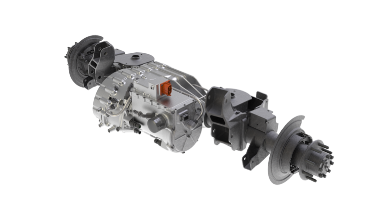
No-Compromise Propulsion for the Heavy-Duty Electric Pickup
How a 2-speed integrated e-Beam axle removes the final barrier to practical heavy-duty electrification Dan Ouwenga, Director – Product Management, Dauch The promise of electric propulsion has always been straightforward: instant torque, smooth drivability, reduced NVH, and lower lifetime operating costs. For light-duty passenger vehicles, that promise has largely been delivered. But for the heavy-duty […]
Continue reading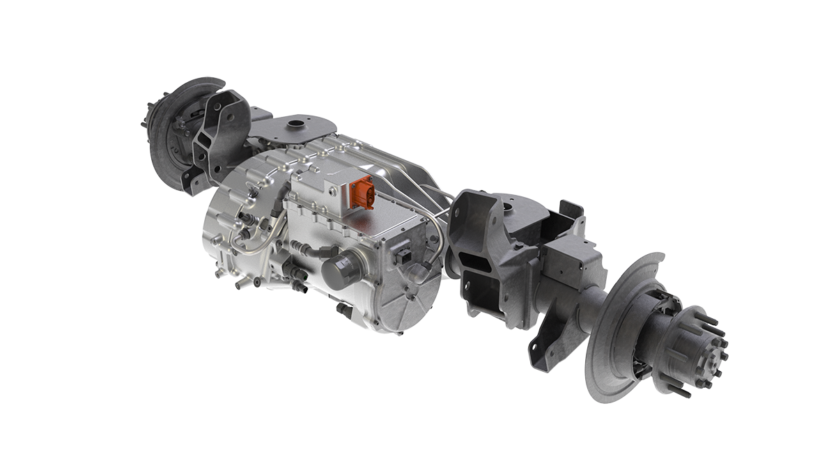

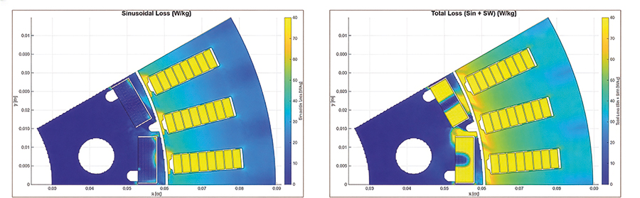
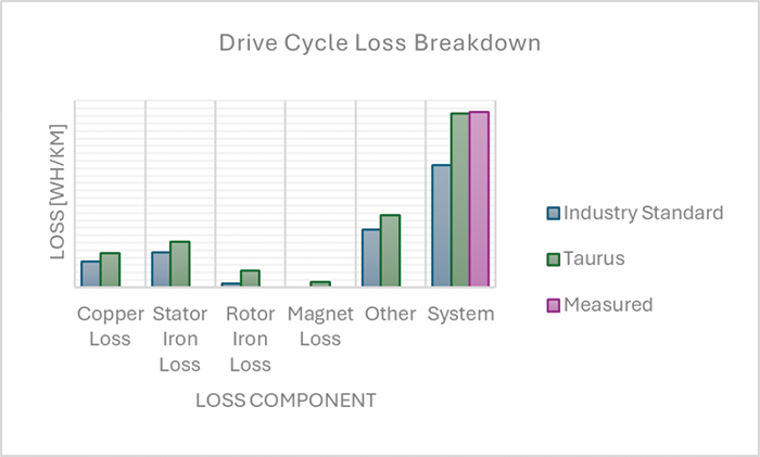
Taurus: a powerful mix of industry standard and lessons learned through experience
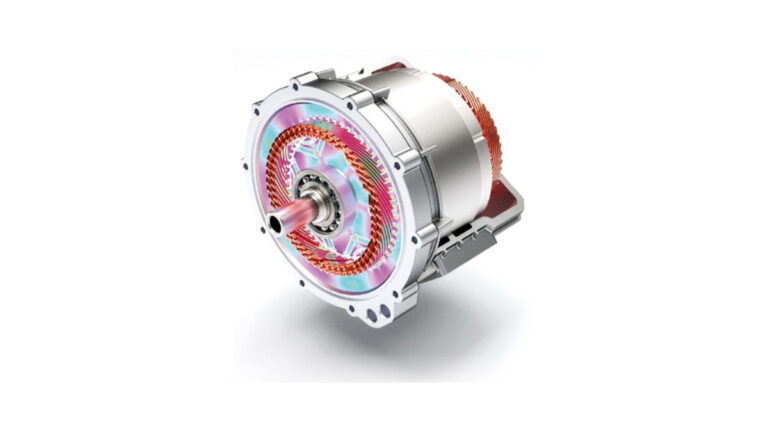
Automotive drivetrain engineers aim to perfect and refine electric drive lines to the point where they operate right at the edge of what is physically possible. This requires simulation models, to act as cost function in the design process or to train reduced order models. These latter models should incorporate all physical loss and performance […]
Continue reading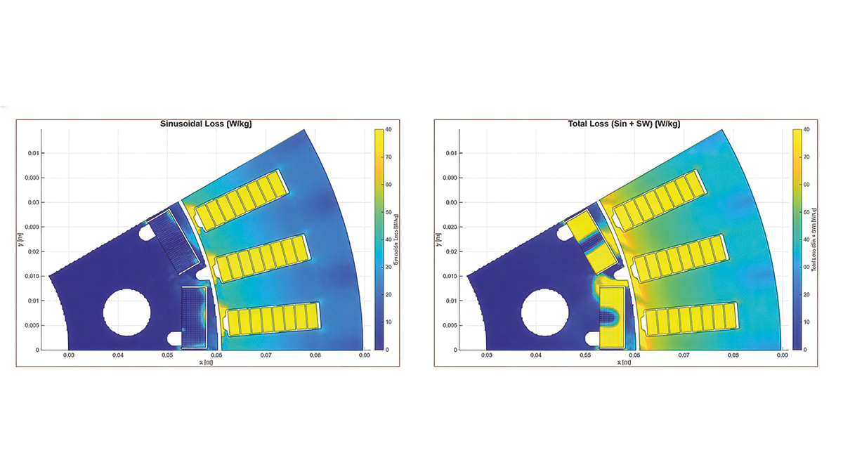
How deeptech is already revolutionising EV powertrain engineering
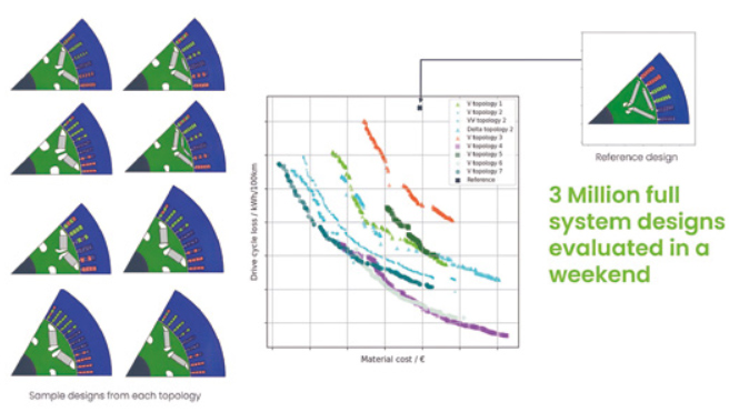
Simon Shepherd, Head of eDrive and Chief Product Officer, Monumo Deeptech is transforming EV powertrain engineering by introducing new levels of computational freedom, speed, and system integration, allowing companies to achieve levels of performance and cost reduction previously out of reach through existing methods.
Continue reading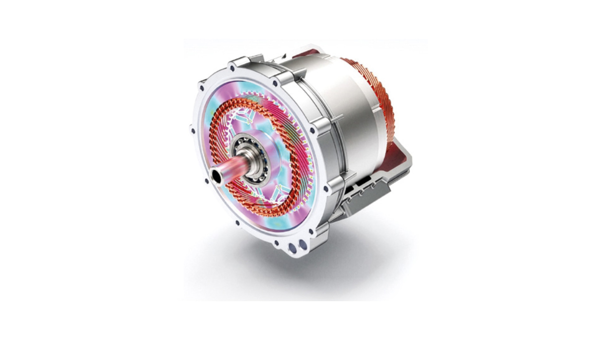

AI-Powered Engineering Software for Electric Drives: OPED
Boosting powertrain development with agility, fast time-to-market and optimal product-market fit Dr. Martin Hofstetter, Head of E-Mobility and Alternative Drivetrains Research Group, Graz University of Technology Dr. Dominik Lechleitner, Senior Researcher, Graz University of Technology Designing electric powertrains is challenging: engineers must quickly find competitive designs and optimize the system for multiple key performance indicators […]
Continue reading
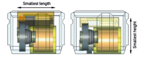
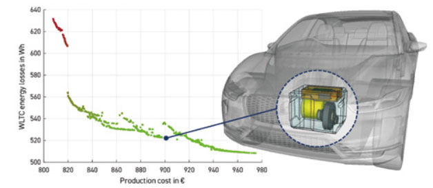
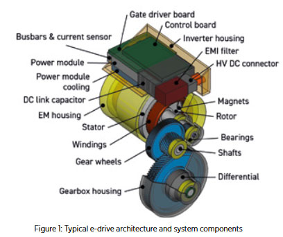 The development of electric drives (e-drives) is a highly complex and interdisciplinary process. Engineers must simultaneously design numerous electrical and mechanical subsystems (see Figure 1) that must optimally work together while meeting ambitious system targets for performance, efficiency, cost, and packaging. These objectives are often conflicting – improving one typically worsens another. Moreover, this highly challenging task must be solved under strong time pressure as it is critical for ambitious time-to-market goals. Therefore, engineering of electric drives demands digital tools capable of handling multi-criteria optimization and cross-domain interactions in an integrated way to quickly provide solid answers to complex questions.
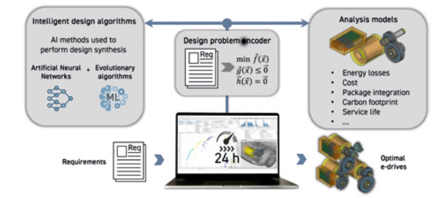

From Lab to Exhaust: A Startup’s Breakthrough in CO2 Transformation
Alicja Stankiewicz, CTO, Coat-It Marek Turkiewicz, CEO, Coat-It Pollution kills more people globally each year than war, hunger, or disease. And at the heart of this crisis is carbon dioxide (CO2) – the primary greenhouse gas driving climate change.But what if CO2 could be split and transformed before it ever leaves a tailpipe?
Continue reading
Data Driven Cost Measure Generation for Automotive Systems Using Teardown Intelligence and AI
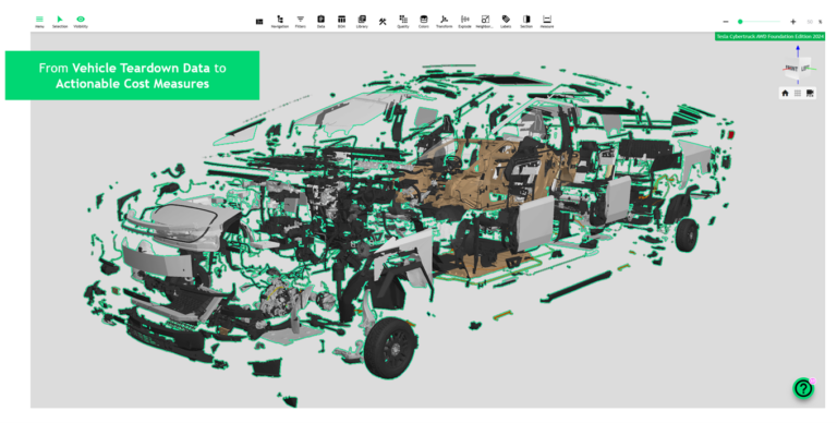
Ivan Jovanovic, Team Leader Incubation InnoHub Cost optimization in modern drivetrain systems requires more than benchmarking—it demands structured, data driven ideation. This article presents an AI supported methodology that leverages largescale teardown intelligence to systematically generate and assess cost measures at component and system level. The approach bridges the gap between engineering detail and cost […]
Continue reading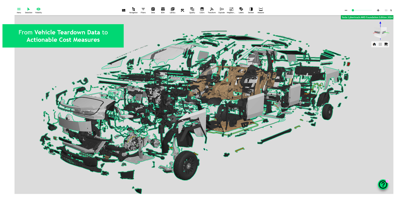
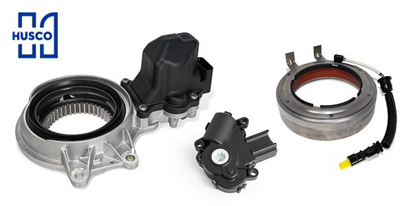
Husco Automotive: Engineering Solutions That Move Mobility Forward
Steven Musbach, Account Manager Husco Automotive is a global engineering and manufacturing partner delivering advanced actuators, valves, and fluid control solutions for automotive applications across internal combustion, hybrid, and electrified vehicle platforms. With decades of systems‑level expertise, Husco collaborates closely with OEMs and Tier 1 integrators to develop production‑ready technologies for driveline, engine, and transmission […]
Continue reading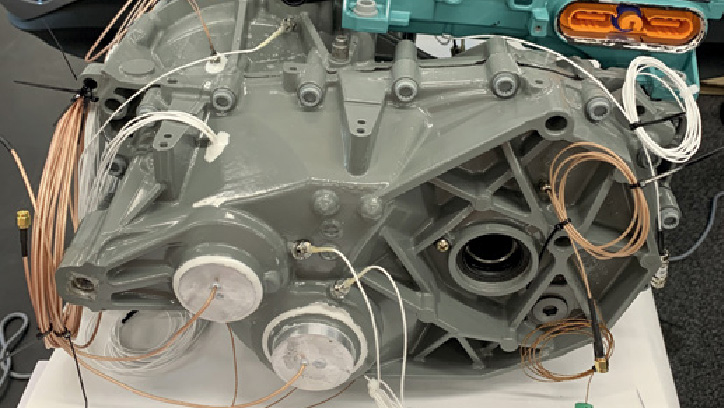
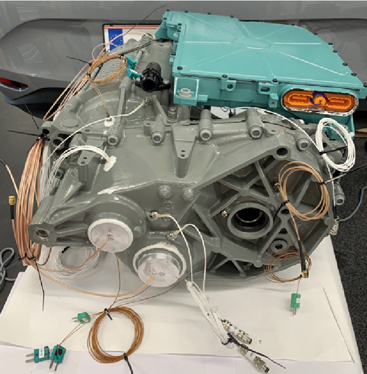
Best-in-class Thermal Assessment of Electric Powertrain
Mario Theissl, CEO, Theissl Systems GmbH THEISSL systems enables precise measurement of temperature and torque in electric drive units with its minimally invasive sensor telemetry technology that is tailored specifically to each customer application. These systems can be seamlessly integrated into existing drive components with minimal need for system modifications, allowing for highly accurate measurements […]
Continue reading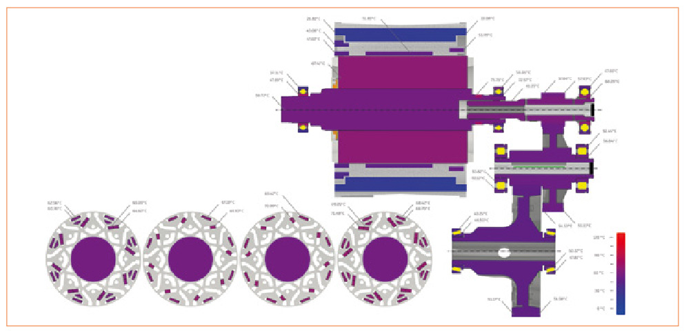
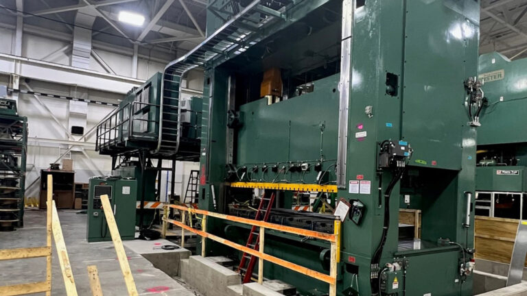
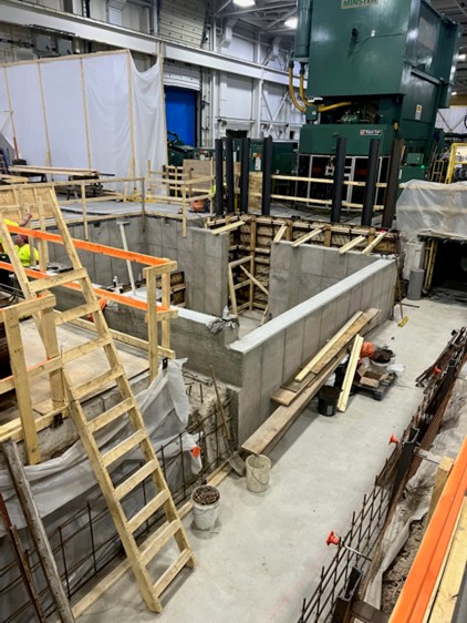
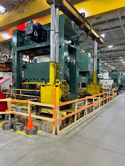
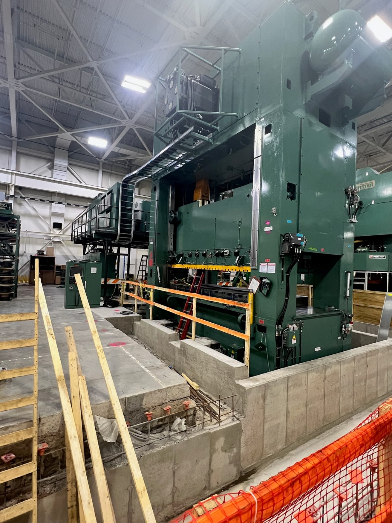
A.J. Rose Installs World-Class Equipment in Response to Industry Trends
Electric vehicles are revolutionizing the automotive industry in a way that has not been seen since the seatbelt became mandatory in 1967. Competition among OEMs is increasing and the modern day ‘race to the moon’ is underway, lead by manufacturers such as Volkswagen, Ford, GM and Volvo as they roll-out EV & hyrbid models off […]
Continue reading