News


News from cti-symposium.world

Ultimately, it comes down to BEV and hydrogen
Interview Dr Manfred Schuckert, Head of Regulatory Strategy & Int. Hydrogen Strategy, Daimler Truck AG Long-distance transport accounts for a large proportion of CO2 emissions. So, is full electrification the only sensible way forward? We spoke with Dr Manfred Schuckert, Head of Regulatory Strategy & Int. Hydrogen Strategy, Daimler Truck AG, about the challenges and […]
Continue reading
Ultimately, it comes down to BEV and hydrogen
Interview Dr Manfred Schuckert, Head of Regulatory Strategy & Int. Hydrogen Strategy, Daimler Truck AG
Long-distance transport accounts for a large proportion of CO2 emissions. So, is full electrification the only sensible way forward? We spoke with Dr Manfred Schuckert, Head of Regulatory Strategy & Int. Hydrogen Strategy, Daimler Truck AG, about the challenges and alternatives − and what he would like to see from regulators.
The European Emissions Regulation favours BEV quite consistently. From a regulatory viewpoint, which drives look promising for commercial vehicles from 2030 onwards?
To make a substantial impact on fleet emissions, commercial sector vehicles need to be either zero emission, or virtually zero emission. So ultimately that means battery electric drives, but also hydrogen for fuel cells and combustion engines. Plug-in and full hybrids will contribute too, of course, but only in a minor role. Two-thirds of emissions come from long-distance traffic, so strict decarbonization is a must.
What opportunities do you see in long-distance transport for biofuels or even e-fuels?
When you really look at the big picture and see how the European commercial sector is currently Burning 60 million tons of diesel, we don’t see a significant role for biogas, meaning CH4 or biologically produced methane. Of course, you also have HVO − Hydrotreated Vegetable Oils − and FAME, the classic biodiesel. We’re cautious about FAME because there are quality issues and because it gets into the engine oil, which means shorter oil change intervals, etc. That’s why we recommend only use it as B7 or B10 in small quantities. And when you look at global capacities, availability of HVO is very limited. Global production capacity currently stands at roughly 6 million tonnes, a drop in the ocean compared to the amount of diesel, we are burning every day.
What differences do you see in major markets like North America and India?
You can certainly see differences. The American market is very mileage-oriented. Basically, you have vocational vehicles and long-haul vehicles that must be extremely efficient to succeed. Not many Operators today are using natural gas for long haul transportation, for example. Alongside battery-electric vehicles, hydrogen will certainly play a role.
Some people claim BEVs will work for long hauls in North America, too, because it’s cheap to buy land and build the infrastructure inland.
I think the follow-up costs at the charging stations would be more important than land prices. The grid is not that powerful and stable, so large-scale electrification is scarcely possible at the moment. There are about 3000 subnetwork operators in the US, and their biggest task right now − integrating data from computer centers aided by AI − is already making them borderline unstable. If you want widespread electrification for passenger cars or trucks, that would work in individual areas, but definitely not across the board in the next ten years.
Which drive concepts do you favor for different vehicle segments, from distribution to long haul?
Where electricity is cheap locally, in depots or towns, that’s the home turf for battery electric trucks. As distances grow, hydrogen can definitely come into play, too. You can’t install charging stations at construction sites, for instance. For long-haul work, there is no clear-cut either-or, so we expect to see fuel cells as well as battery-electric drives. By long haul, I don’t mean just 500 km; I also mean − to use a classic example − trips with two drivers who bring strawberries from southern Spain to Hamburg for example. The product needs to reach the customer fast, so you can’t spend many hours recharging en route. It also needs to be cooled − and the electricity for that comes off your vehicle range.
Which type of hydrogen storage for fuel cells will prevail – LH2 or CGH2?
That’s not really a question for us. Given the quantities we need for long hauls, we’ll only transport liquid hydrogen. Otherwise, the transport costs would be prohibitive. A typical tanker truck will carry either about three tonnes of liquid hydrogen or 500 kg to a tonne of gaseous hydrogen. Distribution costs are so high, it just doesn’t add up. Secondly, you can convert liquid hydrogen to gaseous hydrogen at the filling station so that the filling station can offer both options. It’s a relatively efficient process.
How much power does liquefaction use?
The latest plants use about 8 kW for liquefaction, and the per-kilo energy content of hydrogen is 33 kWh. So, that’s roughly 20 percent of the energy content for liquefaction. But that will improve. We’re already seeing 6 kW on the horizon. But this doesn’t mean you lose range in the vehicle − quite the opposite. You lose a little during electrolysis, and then the hydrogen is liquefied and transported. Then, you can refuel the vehicle with minimal energy expenditure. This filling station type is far cheaper than filling stations for gaseous hydrogen, so we see substantial cost benefits there.
How hard is it to transport liquid hydrogen over longer distances?
You can carry about 70 kg of liquid hydrogen per cubic meter, which is much better than if you had to transport it in gaseous form, where you might manage 40 to 50 kg at 700 bar. The transport tanks for liquid hydrogen are basically vacuum flasks − double-walled and vacuum-insulated. We use them for transport from the production site, and also in the vehicles. On a truck, you have two tanks that you can fill with 80 kg of hydrogen in 10 to 12 minutes. It works the same on a larger scale − you can bring hydrogen in from the Middle East the same way as you do LNG. The tanks are so well insulated that it works over long distances. The only noticeable losses are the hydrogen you use to power the ship.
What would you like to see from European regulators to help you develop technical solutions effectively?
We need to streamline the regulations. And we need to question whether the speed of the Regulation is actually manageable. We only have 5 to 6 years to go, to reach the 2030 targets − a reduction of of 45 % CO2 emissions compared to 2019. We’ll have to see whether the customers can manage that. At the moment, multiple member states are not meeting their obligations, neither for infrastructures, nor for the implementation of CO2-based road toll systems. Without greater unity and faster infrastructure rollouts, customers have no incentive to buy electric vehicles.
Interview: Gernot Goppelt

The two-wheeler and passenger car segment in India is growing significantly
Interview Amid Gupta, CEO and Managing Director, Hero Motors The Indian car market recently became the third largest worldwide and still offers excellent growth prospects. We asked Amid Gupta, CEO and Managing Director at Hero Motors, about the unique features of the Indian market and the company’s plans for Europe.
Continue reading
The two-wheeler and passenger car segment in India is growing significantly
Interview Amid Gupta, CEO and Managing Director, Hero Motors
The Indian car market recently became the third largest worldwide and still offers excellent growth prospects. We asked Amid Gupta, CEO and Managing Director at Hero Motors, about the unique features of the Indian market and the company’s plans for Europe.
Many people know Hero Motors primarily for its two-wheelers. What are your activities in the automotive field?
Our brand is widely recognized as a leading player in India for two-wheelers and bicycles. Over the past few decades, our group has diversified into automotive components. Hero Motors‘ core focus is on automotive components, particularly powertrain solutions, with business activities in Asia, Europe, and the US. With facilities in India, Thailand, and the UK, we manufacture complete transmissions for motorcycles and performance cars. With recent investments, we can deliver comprehensive value chain solutions, including design, validation, prototyping, and serial manufacturing of transmission components and systems.
What are Hero’s plans for more automotive business in Europe?
We have maintained a strong presence in Europe for many years, with some of our relationships with OEMs spanning 10 to 15 years. Our customers trust our technology, quality, and collaborative approach, which we continue to build upon. In addition to our UK office, we plan to open a new office in Frankfurt to enhance synergies with our European customers. Moreover, we are actively exploring opportunities to establish a new facility or acquire an existing one in Europe to support final assembly operations for EV components, such as transmissions, motors, and inverters, closer to European customer locations.
You gave interesting insights into the Indian market at the CTI Symposium Berlin. To what extent will passenger vehicles replace two-wheelers on a larger scale?
India’s market is unique, with 60 % of the population living in rural areas and 40 % in metropolitan regions. While people in cities aspire to own cars, many in rural areas face financial challenges that make car ownership difficult. However, with a population of 1.43 billion, even the 40 % urban segment represents a significant opportunity for the automotive market. Currently, less than 3 % of the population owns a car, and last year, two-wheeler sales were roughly four times higher than car sales. For many Indian customers, two-wheelers serve as affordable, practical commuting vehicles, so the two-wheeler market remains significant. There’s substantial growth potential for both the two-wheeler and passenger vehicle segments as both continue to expand.
We remember the Tata Nano, which failed to meet expectations at the time. How do today’s potential car buyers in India differ from people in Europe or North America in terms of expectations?
The Indian car market is not focused on the super-premium segment. Combined sales of premium brands like BMW, Volvo, Volkswagen, and Mercedes total only about 40,000 cars annually, making up roughly 1 % of the market. It’s important to note that premium cars in India are taxed differently; for example, a BMW car that costs 100,000 Euros in Germany is much more expensive in India. Most Indian buyers aspire to buy mid-premium cars, typically priced between 12,000 and 20,000 Euros, and they seek cars with a full range of features. Within this price range, there is a growing preference for SUVs, driven partly by road conditions. As in other regions, SUVs are becoming increasingly popular among Indian consumers, forming 43 % of the market in 2023.
What role does electrification play in India, and what are the specific requirements compared to Europe?
The Indian government is actively promoting electrification, with a strong focus on encouraging the development of charging infrastructure and battery-swapping systems, which are gaining significant momentum. Major OEMs also align their strategies with this shift, making substantial investments in the electric vehicle space. Electrification is particularly well-suited for three- and two-wheelers in India, thanks to their lower range requirements and smaller battery sizes. However, plug-in hybrids are becoming increasingly popular for cars, as they alleviate range anxiety and offer a practical solution for drivers. Personally, I would choose a hybrid, as it reduces emissions while providing peace of mind, even in areas where charging infrastructure is limited. While mild hybrids remain familiar, the growing popularity of plug-in hybrids reflects increasing consumer recognition of their advantages.
How is the energy and charging infrastructure developing? Where will BEVs penetrate the market on a large scale?
India’s energy and charging infrastructure is developing, but it’s progressing more slowly than Europe or China. Currently, only 2 % of cars are electric, though this is expected to rise to 30% by 2030. The adoption of electric cars has been slower than for three-wheelers, which require less complex charging infrastructure. Electric three-wheelers currently make up 54% of the market, with projections showing they could reach 70% by 2030. For two-wheelers, 5 % are electric today, with expectations of 50 % by 2030.
Interview: Gernot Goppelt
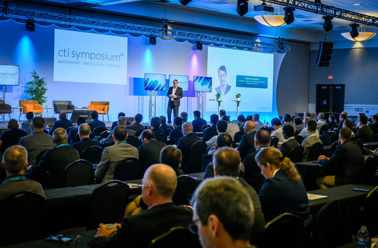
Event Report CTI SYMPOSIUM USA 2025
Software Increasingly Defines the Powertrain Ten years ago, transmissions were still seen as the ‘managers of the drive system’. Since then, the focus has shifted entirely. At the CTI Symposium Novi 2025, key topics included the diversity of electrified drive systems, new solutions such as Range-Extended Electric Vehicles, current challenges in electronics and battery development […]
Continue reading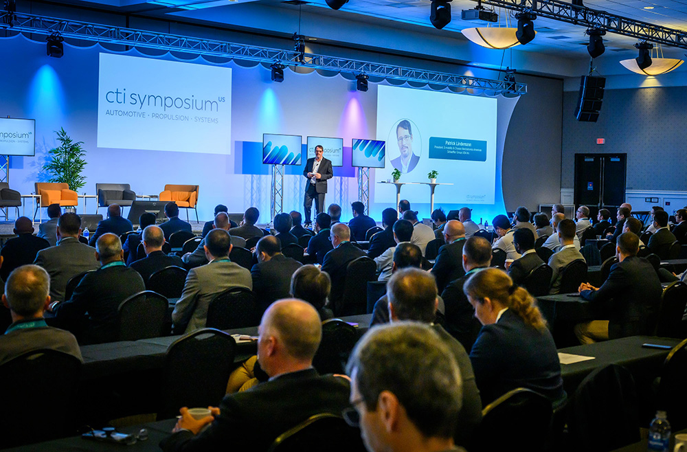
Event Report CTI SYMPOSIUM USA 2025
Software Increasingly Defines the Powertrain
Ten years ago, transmissions were still seen as the ‘managers of the drive system’. Since then, the focus has shifted entirely. At the CTI Symposium Novi 2025, key topics included the diversity of electrified drive systems, new solutions such as Range-Extended Electric Vehicles, current challenges in electronics and battery development – and the Software-Defined Vehicle, which is also redefining drive development.
Sometimes, it can seem as though the Chinese automotive industry is inexorably outpacing Europe and North America. But in his introductory speech in Novi, CTI-USA Chairman Patrick Lindemann was far more upbeat. He invited his audience to see the bigger picture: Yes, over 30 million cars were sold in China in 2024, against just over 10 million in Europe and around 18 million in the USA (15 million of which were non-imports). But in Europe, the average car price was around $56,000, compared to $23,400 in China. At roughly $49,000, American vehicles were cheaper than in Europe – but in terms of total market sales, the USA led the field with $882 million, while China managed just $730 million, only slightly more than Europe. The bottom line: The US market is still the biggest. So as Lindemann put it: „Let’s discuss at this symposium, what the best drive technology is for the US market.” This much is clear: drive systems diversity will be around for a while, there is a new kid in town called REEV, and the Software-Defined Vehicle has already arrived. The focus of value creation is shifting – and that means excellent opportunities for the US industry.
Electrification: slow, but steady growth
Since these ‘best drive technologies’ will increasingly be electrified in North America, too, a review of the „Electric Vehicle Ecosystem” in the USA is a good place to start. In his presentation „US EV Industry Update”, Brent Gruber of J.D. Power said there was continuous growth in BEVs and HEVs, but PHEVs were still not really gaining traction. In 2025, HEVs accounted for 13.2% of all new registrations; BEVs achieved 9.5%, and PHEVs just 2.2%. Over the past three years, the number of BEV models in the market had risen from 27 to 62, most of them in the premium segment. Gruber asked why the EV market wasn’t growing faster. One reason, he said, was political uncertainty concerning tax incentives. But unless registrations grew faster, the US would miss its emissions targets. Charging infrastructures were another issue. Satisfaction levels were actually dropping here: 19 percent of EV drivers reported non-functioning charging stations, and the number of EVs was growing twice as fast as the number of charging stations. On the other hand, more than 4 in 5 people charged at home, while the average EV user drove less than 50 miles a day. Nevertheless, J.D. Power expects EVs to grow their market share from 2026 onwards, and predicts roughly 26% by 2030.
Range Extenders for the USA too?
REEVs (electric range extended vehicles) are very successful in China, alongside BEVs. Given the sheer size of the USA, could they make sense there too? At the symposium, the acronyms REEV and EREV were both used, and are interchangeable. Joe Tolkacz presented the Stellantis Ramcharger, calling it the „right vehicle at the right time” for the US market. The RAM 1500 Ramcharger is the first light truck in an REEV format, and the performance data are impressive. The independent electric drives on the front and rear axles deliver 250 and 248 kW respectively, while the V8 combustion engine supplies up to 202 kW to a generator with 202 kW peak and 130 kW continuous power. The battery capacity is 91.8 kWh, and Stellantis puts the total range at 690 miles. Being a light truck, the Ramcharger comes with an automatic transmission, plus a range of extra modes such as snow, trailer or off-road. Of particular interest to US customers is its V2X (Vehicle to X) compatibility, which means the Ramcharger can supply power to tools, other vehicles, and also to homes. This generator function is the main differentiator between the Ramcharger and a normal BEV. It can power a home for 11 to 22 days on a single tank of fuel, or even a whole neighborhood if refueling is an option – in theory, for as long as necessary.

At the symposium, opinions differed as to whether REEVs will really have a future or not. During the OEM panel discussion, Micky Bly, Stellantis, said a vehicle like the Ramcharger made sense because it could fully meet all consumers’ everyday needs. Stellantis currently offers two systems – the REEV for large body frame applications, and P2 PHEV solutions for models like the Jeep – and intends to pursue both options. Norman Peralta, GM, said PHEVs made sense for large cars and trucks since customers do not want to buy a BEV with today’s battery technology. Like his colleagues at Stellantis and GM, Thomas McCarthy said Ford wanted to give consumers a choice and would therefore keep supporting drivetrain diversity. Dante Boutell, Toyota, foresees a gradual shift from PHEV to REEV, but said BEV would ultimately prevail, especially if ranges continue to grow. During the Q&A session after his presentation, J.D. Power expert Brent Gruber made it quite clear that, in his opinion, REEVs, like PHEVs, were neither fish nor fowl – and were unlikely to take a sizable share of the market.
Electrification of Large and Work Trucks
The Truck Electrification Panel discussed the best drive system for large trucks. Jason Gies of Windrose thinks long-haul trucks will be fully electrified, too. He said Windrose was currently pursuing BEVs only, with ranges of up to 420 miles and a charging time of 38 minutes from 20-80% SOC. However, a high-performance charging infrastructure was „hypercritical.” By contrast, as Jerome Gregeois explained, Hyundai-Kia is pursuing three options: BEV, fuel cell, and EREV. Andreas Kammel of Traton also saw room for all options, depending on the application, but said, plug-in solutions were a niche, and BEV would also prevail in long-haul applications. Kevin Robinet of Scout said designing REEVs as a BEV architecture variant for smaller applications would make sense. „If BEV energy density quadruples, everything speaks for BEV – but when is that going to happen?” According to Ruidong Yang, BYD is also backing purely battery-electric drive systems for long-range trucks. He said REEVs made sense for some applications, but were technically more complex, and ultimately yielded less range per kilowatt.
As Chad Smith, Oshkosh, showed in his presentation „Advancing Powertrain Solutions for Work Trucks”, electrifying vocational and work trucks comes with its own set of requirements. Vocational trucks are commercial vehicles whose primary function is to „work.” Depending on the application, electrification levels vary greatly. Concrete mixers, for example, need to run continuously, so they are either HEVs, or ICE-only. Oshkosh also offers BEV garbage trucks with high recuperation levels, and a battery designed for the vehicle’s lifetime. Charging is not an issue here, he said, as operators had their own charging stations. Smith said Oshkosh also offered PHEV rescue and firefighting vehicles for airports. These had 28% better acceleration and sufficient range for normal daily use, and „German customers love them.” Military vehicles were a completely separate category; charging in an austere environment was impractical. That said, an HEV design made sense and could cut consumption by up to 30 percent, whereby the extra weight and complexity needed to be factored in. Smith finished up by mentioning several challenges in work truck electrification, including training and service for high-voltage applications, the availability of drive components, and ensuring the future availability of domestically produced batteries. Given the short production runs for work trucks, he said, the supply situation was more difficult than for large-scale manufacturers.
Battery Production as seen by a Volume Manufacturer
By contrast, Stellantis has to master large-scale production requirements on an international scale. Tim Grewe, Stellantis, talked about the challenges of „STLA Multi Energy Battery Systems & Industrialization”
in HEVs, PHEVs and BEVs. For example, Stellantis has to deal with the fact that European cars are smaller than American vehicles. Hence, the company portfolio includes three unibody platforms (small, medium, and large) with electric ranges of 300 to 500 miles, plus a body-on-frame platform for trucks with a range of up to 500 miles. The frame platform was just as suitable for ICE drives as for BEVs, FCEVs, xHEVs, and REEVs such as the Ramcharger. Grewe noted that Stellantis already offers 30 hybrid models in Europe under its Alfa Romeo, Fiat, Citroën, Peugeot, Opel, Jeep, and Lancia brands, with six more to follow in 2026. He said Stellantis tackled one major task over ten years ago, by standardizing battery production across all global locations. Using a cloth stretched across the stage, the speaker effectively demonstrated how delicate battery separators are and how critical even the slightest damage is. „You put a hole in it, and the lithium is going to find a way to cause trouble.” This applied to all batteries: hybrid batteries may have different and more frequent duty cycles, but the core requirements for production reliability were always the same. Each location needed be able to produce everything. Standardized processes were essential in order to meet customer needs quickly, globally, and promptly.
The Road to Software-Defined Vehicles
Lucid Motors is at the other end of the spectrum. It makes just two EV models – the Air and the Gravity – and follows a rigorous in-house development approach. In his lecture „Vehicle Efficiency Through Integrated Design of Drive Units and HV Battery”, Emid Diala described how Lucid developed most of its hardware and software in-house, from the battery system and electric motor to the power electronics and beyond. The company also designed its own development software. This enabled it to model and simulate all components and the overall system as early as possible. Before the first prototypes were built, developers even balanced battery properties (such as charging speed) and driving capability in the simulation. For Lucid Motors, its vehicles were the best examples of Software-Defined Vehicles (SDVs) – not just in terms of OTA software updates, but also in the high degree of hardware and software integration along the whole development chain. This would not have been possible using bought-in modules.
SDV in general is playing a growing role at CTI symposia, as illustrated by the presentation „Continuous Everything – Automotive in Transition to Becoming a Software Industry” by Florian Rohde, iProcess. Before becoming a consultant, Florian Rohde worked at Tesla on the Software-Defined Vehicle, „which wasn’t called that back then.” Up till now, he said, dealers sold and serviced cars. But today, you could retrofit features via software, and sometimes even sell them as a service. You could update the user interface, interact with customers, have a complete feedback loop, offer preventive maintenance, and avoid physical recalls. All of this required software-oriented processes and work structures. Using Tesla as his example, Rohde described how making changes to both software and software involved basing the work on schedules, as opposed to features. „If you have a software feature ready on time, it can go into the release train; if not, you have to stay where you are.” Traditional, component-based development also no longer made sense. Since the hardest aspect was integration at system level, everyone had to be in constant communication. It was vital to bring all the developers together as early as possible, and to test vehicle functions continuously and automatically throughout development. „When people are developing a new feature, allow them into the car”, the speaker explained. „Allow what is called feature branches.” In other words: develop features in an encapsulated environment, then integrate them back into the higher-level software tree.
From the developer viewpoint, Software-Defined Vehicle seems set to replace traditional component-based development rapidly – and not just in BEVs, as Florian Rohde noted. Feature-oriented development offers new possibilities, and new customer benefits. As Emid Diala put it: „An SDV doesn’t age during operation, it actually becomes more modern in terms of functionality.” Christine Thelesklaf, the Bosch representative on the Supplier Panel, added that in terms of brand differentiation, drive systems would matter less, while the way brands integrate their electronics and design their user interfaces would become more important.
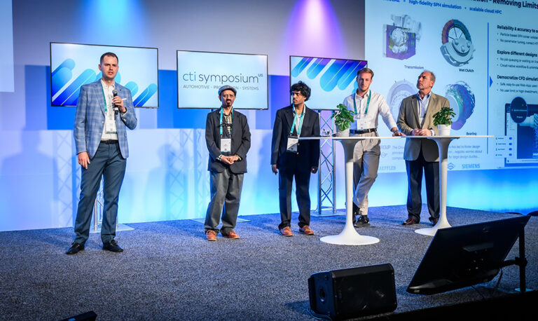
Deep-dive contents and a new forum for innovative startups
The CTI Symposium Novi offered a comprehensive program of deep-dive presentations in addition to the plenary presentations and panel discussions. There were 53 in all, grouped under the following session headings: Electric and Hybrid Drives, E-Drive Components, E-Motors, Batteries, Thermal Management, Development Tools, AI & Testing, Commercial Vehicle Propulsion, Development Tools, Testing, and Lubrication.
In a new format that will be repeated at future events, seven startups introduced themselves briefly during the two days, and offered guided tours of their exhibition booths. For this new format, CTI has partnered with GAMIC, a non-profit organization with the mission to identify, mentor, and promote global startup innovations targeting the North American mobility market.
Dive Engineering Software offers a browser-based smoothed particle hydrodynamics software that enables virtual drivetrain lubrication and cooling analysis. EcoNova Tech has developed innovations using the Geneva mechanism or non-circular gears for uninterrupted shifting with EVs. eLeap-Power provides advanced power electronics solutions tailored for off-highway, light commercial, and passenger vehicle applications. Emil Motors is working on the next generation of electric motors, being entirely free of rare earth material. Limestone Engineering Services (LES) offer consultancy in areas like transmissions, ICE, BEV and specific fields like FE analysis, NVH, tribology etc. Marel Power Solutions is a power electronics company, focused on advancing electrified powertrain systems. Orbis Electric’s patented technology is a lightweight axial flux motor-generator with unrivaled power & configurability.
Software, Electronics, and Semiconductors are growing
Summing up, North America will continue to see a diverse range of drive concepts in years to come. Given the sheer distances involved, a one-size-fits-all solution seems unlikely to appear anytime soon. Will the relatively new vehicle category of REEVs gain traction in the USA too? We look forward to monitoring developments in this sector. One strong argument in their favor is their ability to serve as power generators, including in V2X applications. But as the discussion at Novi made clear, P2 PHEVs may still have their place wherever ICE hauling power has priority.
The trend towards software-defined vehicles is evident. SDV offers new service models, streamlined development processes, and tangible extra consumer benefits. How far will Software as a Service go? Will we eventually just sell functionality, not vehicles? Other areas whose growth will be matched by their coverage at future CTI Symposia include power electronics for electrified drives, where interesting advances are being made in the field of power semiconductors. What role can GaN play as an alternative to SiC, for example? Will highly efficient inverters trickle down to lower-cost applications? At the CTI Symposium Berlin (December 2 and 3, 2025, Estrel Hotel, Berlin), all this and more will be up for discussion.
4 Steps to Optimizing Sustainable Design and Manufacturing
aPriori’s four-phase sustainability maturity model integrates sustainable practices into manufacturing while balancing profitability and environmental impact This framework guides manufacturers toward environmental stewardship using data-driven insights to make effective design, sourcing, and production choices
Continue reading
4 Steps to Optimizing Sustainable Design and Manufacturing
aPriori’s four-phase sustainability maturity model integrates sustainable practices into manufacturing while balancing profitability and environmental impact
This framework guides manufacturers toward environmental stewardship using data-driven insights to make effective design, sourcing, and production choices
Designing products that balance profitability and sustainability is essential in today’s market. This requirement is driven by a growing consumer demand for greener products, stricter environmental regulations, and a collective push to achieve carbon reduction targets.
Manufacturers must integrate sustainable practices into their existing operations without compromising on efficiency or competitiveness. This raises a pivotal question: How can manufacturers align their operations to promote environmental stewardship and spur growth?
To address this critical issue, aPriori has established a sustainability maturity model as a strategic roadmap for manufacturers to assess their current capabilities and the effectiveness of their green supply chain management initiatives. By monitoring their sustainability maturity performance, manufacturers can establish clear steps to reduce their carbon footprint.
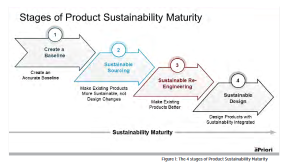
The following figure illustrates how product development teams can assess and pinpoint their position across the four stages of sustainability maturity.
Manufacturers that don’t advance their sustainability maturity to the fourth and final stage risk falling behind their competitors and being saddled with additional operational costs due to incurred carbon taxes and other regulatory policies enacted to spur the reduction of greenhouse gases (GHGs).
Learn more by downloading the aPriori Sustainability Guide at get.apriori.com/CTI-mag
Stage 1: Create Precise, Auditable CO2e baselines
Creating an accurate carbon emissions baseline is the first step in achieving a sustainable and green supply chain. This baseline empowers sustainable manufacturers to measure and quantify the carbon footprint of their existing supply chain operations, enabling them to:
- Use their current “state of sustainability” as the starting point to plan and track their progress
- Identify and focus on the areas with the highest cost and carbon reduction potential.
- Set realistic cost targets that guide and influence product teams’ supply chain decisions.
- Adhere to environmental, social, and governance (ESG) standards and regulations.
- Benchmark and compare their sustainability performance against industry competitors.
Life cycle impact assessments (LCIAs) are a standard method to establish CO2e baselines and provide manufacturers with standardized emissions estimates for product lifecycle areas that are impossible to measure accurately.
Carbon assumptions for a product’s in-use phase can be entirely different from reality. A car, for example, could burn fossil fuels for 300,000 miles within the range of established fuel consumption values, or it could be written off in an accident after 1,000 miles. Similarly, a product designed for 90% reuse could still end up in a landfill and not achieve its optimal contribution to the circular economy.
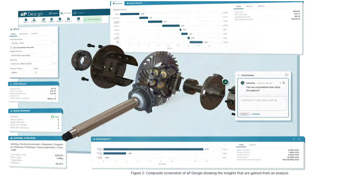
An LCA is a great tool for making assumptions and using averages. How-ever, the manufacturing process doesn’t require that level of guesswork, so a more precise baseline would be beneficial for that phase. aPriori’s automated sustainability insights solution closes the gap by integrating data from ecoinvent, a leading third-party LCA and inventory database tool. aPriori utilizes ecoinvent’s database to quickly establish environmental baselines and Greenhouse Gas (GHG) emissions at the product level. With automated and more precise baselining, teams can quickly move to the second phase of sustainability maturity: evaluating and selecting sustainable suppliers.
Stage 2: Select Sustainable and Responsible Global Suppliers
Next, evaluate and select suppliers based on their local electricity mix, material supply, and processes (Scope 3). Procurement teams can create digital factories for each supplier to see each vendor’s carbon impact, and then compare vendors using the same production criteria (e.g., the same production volume, manufacturing process and equipment, etc.). Digital factories will also show how the energy mix and energy consumption of a supplier in India, for example, compares with production facilities located in Mexico and China. Product teams aim to enhance the sustainability of existing innovations through informed supplier selections instead of resorting to costly design or material changes. Sustainable sourcing offers the most straightforward approach to reducing CO2e by minimizing the need for extensive design changes, and therefore can be implemented at any time. However, it is difficult for product teams to capitalize on this opportunity without a dedicated and standardized tool such as aPriori.
aPriori provides manufacturers with complete visibility into the sustainability of their supply chain, through a digital twin of the manufacturing facilities at their disposal, empowering them to make data-driven sourcing decisions.
By utilizing aPriori for sustainable sourcing, companies can:
- Explore various “what-if” scenarios (regions, routings, materials, volumes/batches, suppliers, make vs. buy).
- Reduce iterations and negotiation by digitally connecting buyers and suppliers.
- Fill skills gaps with exposure to granular, actionable, real-world sourcing data.
- Identify sustainable procurement strategies to support internal ESG goals and initiatives.
Stage 3: Optimize Existing Products for Cost and Carbon
The path toward greener products involves optimizing existing product innovations. In stage three, product teams can consider alternative materials with lower carbon or higher recycled content. And they can also make processes more efficient to improve cost and environmental sustainability, or look to utilize renewable energy sources.
The objective is to minimize cost overruns and release products at target costs to maintain profitability and competitive advantage. However, this is difficult to achieve when cost engineering teams are limited to conventional, labor-intensive costing tools like manual spreadsheets. And the complexity of this challenge heightens when the situation extends to CO2e emissions. This is because spreadsheet-based solutions cannot:
- Evaluate the complex interrelationships between direct and secondary cost & carbon drivers in real time
- Accurately manage cost & carbon variables in an ever-changing global supply chain
- Identify and capitalize on cost & CO2e reduction opportunities during early product design phases
aPriori provides a precise, real-world product cost optimization solution to make highly informed and effective manufacturing decisions. aPriori’s cloud solution can simulate production based on product design (geometry), manufacturing overhead costs, direct labor hours, machine hours, and more. This capability can be fully automated through PLM integration.
Additionally, aPriori enables companies to navigate and manage rising material costs, inflationary pressures, and other external risks to build cost-effective products. aPriori also automatically notifies and provides actionable feedback to design, manufacturing, and sourcing teams when products exceed cost thresholds. This facilitates seamless collaboration among product development teams, enabling them to eliminate cost drivers early and maintain corporate profit margins proactively.
Stage 4: Remove Embodied CO2e Through Data-driven Product Design
The final stage of sustainability maturity represents the most challenging path and the greatest opportunity for reducing GHG emissions. Product engineers can typically compare multiple product designs and intuitively select the most cost-effective option for both cost and DFM. But when you add carbon to the mix, the answer is usually far from obvious.
But by using real-time CO2e feedback from the 3D CAD model, teams can proactively modify the product’s design to reduce its embodied carbon. They can also ensure that a product meets its targets for cost, DFM, and sustainability by selecting the option that best balances all requirements for sustainable design.
Take the Next Step to Optimize Sustainable Design
Optimizing sustainable design and manufacturing is not just a choice: it’s pivotal to addressing today’s market requirements and customer demands. aPriori’s four-step sustainability maturity model presents a comprehensive strategy for manufacturers to align their operations with environmental stewardship while enhancing profitability and market competitiveness.
aPriori’s four-stage model provides a roadmap for best-in-class green manufacturing based on strategic design strategies. It also underscores the need for data-driven insights to make effective design choices amid increasingly complex supply chains. Mature companies in this area will contribute to global carbon reduction efforts and position themselves as leaders because sustainability is increasingly a determinant of success. Once you have the capability for evaluating both cost and carbon during design, and leveraging the same data for sourcing or procurement, you can then start to include the “cost of carbon” as a strategic tool. Leaders in this space are utilizing an internal carbon price (ICP) to convert the units of measure from Kg of CO2e to currency. This is exactly how the Carbon Border Adjustment Mechanism, or CBAM is going to work from January 1st, 2026. This is why it makes a lot of sense to build carbon decision making into the same method as cost decision-making.
Furthermore, evaluations of a product’s cost are rarely left to assumptions or industry averages, but that is usually how the majority of product carbon footprint assessments are done. We all need to care as much about carbon emissions as we do cost. In 2024 alone, it is estimated that climate-related disasters wiped $2 trillion from our economy. That is more than the recession in 2008. In manufacturing, we have both responsibility, but also an opportunity to increase competitive advantage, by reducing the environmental impact of not only the use of the products, but the manufacture of them.
If you are interested to learn more about how you can combine cost, carbon emissions and manufacturability evaluations, based on 3D CAD data, get in touch via get.apriori.com/CTI-mag
The Automotive Industry’s Race to Zero Emissions
Mark Rushton, Sustainability Director, aPriori Technologies Whether it is the end of the road for Internal Combustion Engines or not (due to synthetic fuels), the in-use phase of a vehicle’s carbon footprint will soon no longer be the most significant impact. Tackling embodied carbon proactively and cost effectively is how leading manufacturers are staying ahead […]
Continue reading
The Automotive Industry’s Race to Zero Emissions
Mark Rushton, Sustainability Director, aPriori Technologies
Whether it is the end of the road for Internal Combustion Engines or not (due to synthetic fuels), the in-use phase of a vehicle’s carbon footprint will soon no longer be the most significant impact. Tackling embodied carbon proactively and cost effectively is how leading manufacturers are staying ahead of the competition.
Beyond Tailpipe Emissions
In the automotive industry, we are facing unprecedented challenges with the transition to emission free mobility. Innovation holds the key to success, but some innovations are too expensive to put into production. How can we try new manufacturing processes to get a competitive edge, without detailed cost and carbon footprint analysis of these new processes? Time could be lost experimenting. In this article, we will explore the 4 levels of product sustainabilty maturity that we have identified in customers and prospective customers of aPriori Technologies, from the Automotive Industry and beyond. It also explores various strategies to reduce the embodied carbon in automobiles.

External damping of roller bearings and its effect on the acoustics of an e-mobility gearbox
M.Sc. Kai von Schulz, M.Sc. Tilmann Linde, Prof. Dr.-Ing. Steffen Jäger Furtwangen University, Institute for Product and Service Engineering Reducing the sound emitted by the vehicle and the noise perceived by the passengers is an essential part of the development of modern (e-)vehicles. Bearings are crucial to the transmission of vibrations within the vehicle powertrain. […]
Continue reading
External damping of roller bearings and its effect on the acoustics of an e-mobility gearbox
M.Sc. Kai von Schulz, M.Sc. Tilmann Linde, Prof. Dr.-Ing. Steffen Jäger
Furtwangen University, Institute for Product and Service Engineering
Reducing the sound emitted by the vehicle and the noise perceived by the passengers is an essential part of the development of modern (e-)vehicles. Bearings are crucial to the transmission of vibrations within the vehicle powertrain. This article presents a method for studying the impact of external bearing damping on acoustic properties. For this purpose, damping elements between the outer bearing ring and the gearbox housing of a gearbox used in electric vehicles are introduced, and parameters relevant to damping are varied by means of design of experiments.
Noise sources and sound transmission
At first, the noise sources that occur in a gearbox for electric vehicles will be identified. The gear mesh is determined as one of the primary sources of noise. The vibrations generated by the gear mesh are transferred through the shafts, the bearings, and the gearbox housing [1]. The design and material of the gearbox housing play a crucial role in how these vibrations are transmitted and whether they are dampened or amplified [2]. The vibrations can cause resonance in the housing, amplifying the noise emitted from the gear mesh. The air-borne sound emission occurs when the vibrations from gear mesh and structure-borne sound radiate into the surrounding environment. Due to deviations in the ideal meshing, a transmission error occurs between the driving and driven gear. The transmission error is primarily influenced by the manufacturing tolerances, variations in gear tooth geometry, and operational conditions such as load and speed [3]. The design and manufacturing quality of the gears have a considerable impact on their acoustic characteristics [4]. Moreover, the surface roughness of the gear teeth can influence friction and noise generation [5].
Bearings not only transmit the vibrations introduced by the gear mesh, but can also be a source of noise themselves. The primary sources of noise in bearings occur from various factors including design, manufacturing imperfections, operational conditions, and inadequate maintenance [6]. Factors such as load, speed and alignment are of significant importance. Imperfections in the surface finish of the raceways and the balls or rollers, as well as their roundness, can result in an uneven distribution of loads across the bearing surfaces [7]. The presence of high loads or speeds can exacerbate any existing imperfections in the bearing [8].
Finally, the electric motor can also be regarded as a source of perceptible noise. Electric motors, while quieter than internal combustion engines, introduce their own sources of noise, particularly through torque ripple and electromagnetic interference [9]. Torque ripple refers to the variation in torque output as the motor rotates, which can induce additional vibrations in the gearbox [10]. In addition, electromagnetic interference can cause vibrations in the motor’s components, which may be transmitted to the gears through the coupling, thereby further worsening the acoustic behaviour [11].
Potential noise reduction measures
Following the overview of the noise generation mechanisms within the gearbox, it is evident that specific, targeted measures are required to mitigate the associated noise emissions effectively. The primary noise sources, as described in the previous section, are main areas of concern. Targeted measures in these areas can significantly improve the acoustic behaviour of electric vehicle gearboxes. The authors have examined a wide range of measures for reducing the noise of drive systems [4, 12]. The focus of this article is on damping of the excitation by both the tooth mesh and the ball bearings.
The modification of bearing damping characteristics has the potential to result in a reduction in noise levels [13]. Incorporating damping inserts within or around the bearings of a gearbox is an effective method to absorb vibrations at their source before they are transmitted to the gearbox housing. Materials commonly used for these inserts include elastomeric compounds, viscoelastic polymers, and soft metals which are tuned to absorb specific frequencies of vibrations that are prevalent in gearbox operations [14]. These damping elements are usually placed in the most effective locations in the bearing assembly, where they can absorb the vibration energy resulting directly from the interaction between the rolling elements and the raceways.
Design of experiments on external bearing damping configurations
Design of Experiments (DoE) is a statistical approach to study the impact of multiple factors on the systems performance. In the context of analysing external damping of roller bearings, DoE is applied to evaluate how different parameter sets affect the transfer of the vibrations. DoE is particularly useful in this context, as it enables the identification of the most influential factors affecting both noise levels and efficiency, as well as the optimal combination of these parameters.
The variables in this case are the number of O-rings, their rigidity and the cord thickness of the O-rings, and whether additional oil is pressed into the gaps or not. By allowing simultaneous variation of parameters, DoE not only saves time and resources but also uncovers interactions between these parameters that might otherwise remain hidden. In this way, DoE provides a more comprehensive understanding of how the variables work together to influence the system’s behaviour, revealing possible synergies or trade-offs between different parameters. Here, the focus is on the system’s response in terms of its structure-borne and airborne sound emissions. Additionally, the system efficiency is analysed. For example, reducing the stiffness of the O-rings may reduce the transferred vibration, but it may also reduce efficiency due to a higher transmission error in the tooth mesh. The application of DoE allows the reduction of the number of experimental runs while maintaining the comprehensive coverage of the interactions and effects of all factors within the specified range. This efficiency in test design is critical in experimental research involving complex mechanical systems, where a large number of tests could be impractical due to time, cost, or resource constraints.
Physical study
To evaluate the presented measure of outer bearing damping, an existing high-speed gear test rig (cf. Figure 1) is being converted so that different parameter sets of outer bearing damping can be tested for their effectiveness under different operating conditions, such as speed and torque.
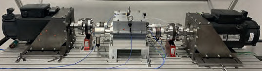
Fig. 1 Gear pair test rig.
For this purpose, the bearing seats have been modified to allow the use of up to three commercially available nitrile rubber O-rings. In addition, it is possible to fill the spaces between the O-rings with oil and apply an overpressure. Figure 2 shows a schematic illustration of the design.
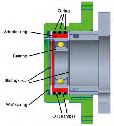
Figure 2 CAD geometry of outer bearing damping design.
In this study, the experimental parameters are varied within specific ranges, providing valuable insights into their effects on system behaviour. Various tests are carried out at different torques and speeds in the range between 0 and 6000 rpm and 0 and 45 Nm. The measurement results are analysed at static operating points. The experimental design includes varying the number of O-rings from 1 to 3 and varying the stiffness of the O-rings between 70 and 90 Shore. In addition, the cord thickness of the O-rings is varied between 1.8 mm and 2.8 mm and whether additional oil is injected into the gaps is also considered as a binary factor (yes/no). Through the application of DoE, this study aims to determine the optimal combination of these factors to achieve an appropriate damping characteristic: significantly reducing noise while maintaining high efficiency.
Once the test rig has been converted and the measurement campaign has been completed, the most promising damping elements will be further optimised.
Authors
M.Sc. Kai von Schulz: Kai.vonSchulz@hs-furtwangen.de
M.Sc. Tilmann Linde: tilmann.linde@hs-furtwangen.de
Prof. Dr.-Ing. Steffen Jäger: steffen.jaeger@hs-furtwangen.de

References
[1] Tosun, M., Yildiz, M. u. Ozkan, A.: Investigation of Gearbox Noise and Comparison of Varying Transfer Path Analysis Methods. SAE Technical Paper 2017-01-1867, 2017
[2] Amaral, D. R., Ichchou, M. N., Kołakowski, P., Fossat, P. u. Salvia, M.: Lightweight gearbox housing with enhanced vibro-acoustic behavior through the use of locally resonant metamaterials. Applied Acoustics 210 (2023), S. 109435
[3] Heider, M. K.: Schwingungsverhalten von Zahnradgetrieben. Beurteilung und Optimierung des Schwingungsverhaltens von Stirnrad- und Planetengetrieben. Zugl.: München, Techn. Univ., Diss., 2012. Dissertationen der FZG / Forschungsstelle für Zahnräder und Getriebebau, Technische Universität München, Bd. 185. München: Verl. Dr. Hut 2012
[4] Schulz, K. von, Linde, T. u. Jäger, S.: Profile Modifications for Gears and their Effect on the NVH Behaviour of an Electric Vehicle Gearbox. 2024 Stuttgart International Symposium on Automotive and Engine Technology. Stuttgart 2024
[5] Zhao, X. u. Vacca, A.: Analysis of continuous-contact helical gear pumps through numerical modeling and experimental validation. Mechanical Systems and Signal Processing 109 (2018), S. 352– 378
[6] Adamczak, S., Stępień, K. u. Wrzochal, M.: Comparative Study of Measurement Systems Used to Evaluate Vibrations of Rolling Bearings. 1877-7058 192 (2017), S. 971–975
[7] Mohd Yusof, N. F. u. Ripin, Z. M.: Analysis of Surface Parameters and Vibration of Roller Bearing. Tribology Transactions 57 (2014) 4, S. 715–729
[8] Wang, Z., Yang, J. u. Guo, Y.: Unknown fault feature extraction of rolling bearings under variable speed conditions based on statistical complexity measures. Mechanical Systems and Signal Processing 172 (2022), S. 108964
[9] Gong, C., Zhang, P., He, S. u. G S J, G.: E-motor NVH Analysis for PWM Induced Current Ripples in EV Applications. 2022 IEEE Energy Conversion Congress and Exposition (ECCE). IEEE 2022, S. 1–5
[10] Novak, W.: Geräusch- und Wirkungsgradoptimierung bei Fahrzeuggetrieben durch Festradentkopplung, Universität Stuttgart Dissertation. Stuttgart 2010
[11] Kim, S. J., Kim, K., Hwang, T., Park, J., Jeong, H., Kim, T. u. Youn, B. D.: Motor-current-based electromagnetic interference de-noising method for rolling element bearing diagnosis using acoustic emission sensors. Measurement 193 (2022), S. 110912
[12] Schulz, K. von, Linde, T. u. Jäger, S.: Measures to reduce the noise emission of a gearbox for electric vehicles. Tagungsband Tribologie-Fachtagung 2024. 2024, S. 394–403
[13] Tsuha, N. A. H. u. Cavalca, K. L.: Stiffness and damping of elastohydrodynamic line contact applied to cylindrical roller bearing dynamic model. Journal of Sound and Vibration 481 (2020), S. 115444
[14] Turnbull, R., Rahmani, R. u. Rahnejat, H.: The effect of outer ring elastodynamics on vibration and power loss of radial ball bearings. Proceedings of the Institution of Mechanical Engineers, Part K: Journal of Multi-body Dynamics 234 (2020) 4, S. 707–722
A.J. Rose Installs World-Class Equipment in Response to Industry Trends
Electric vehicles are revolutionizing the automotive industry in a way that has not been seen since the seatbelt became mandatory in 1967. Competition among OEMs is increasing and the modern day ‘race to the moon’ is underway, lead by manufacturers such as Volkswagen, Ford, GM and Volvo as they roll-out EV & hyrbid models off […]
Continue readingA.J. Rose Installs World-Class Equipment in Response to Industry Trends
Electric vehicles are revolutionizing the automotive industry in a way that has not been seen since the seatbelt became mandatory in 1967. Competition among OEMs is increasing and the modern day ‘race to the moon’ is underway, lead by manufacturers such as Volkswagen, Ford, GM and Volvo as they roll-out EV & hyrbid models off the assembly line. Not to be forgotten are more than 100 ambitious startups looking to make a name in the automotive world. Take a couple steps back in the supply chain and there are countless automotive suppliers watching the competition unfold, excited for the new market opportunities this will bring.
Metal stamping companies make up a large part of the automotive suppliers wondering where they will fit into the electric vehicle landscape. Many likely wondering what their new identity will be 10 years from now. It is certain that metal stampings will remain a major part of the automotive supply chain as we transition to EV, but the type of components that will be stamped is the question mark. A reputable stamping supplier that once specialized in powertrain components may soon find their stamping presses being used for battery trays and EV motor laminations. In order to stay agile and be prepared for any type of stamping coming through the pipeline, a supplier needs two things: First, the the willingness and unity to change even if it’s outside their niche, and second, the necessary equipment and processes to support the evolution.
In the case of A.J. Rose Manufacturing Co., they recently invested in new equipment intended to support the markets of the future. That equipment is a newly-built servo press from Aida. This will be the 58th press at A.J. Rose and also the largest press at 1375 tons. At this tonnage, it opens doors to new markets and product lines with the ability to to produce larger parts and run thicker material. They are adapting to the market, not expecting the market to adapt to them. At a bed size of 191” x 70” and a 20 inch stroke, A.J. Rose will offer more capability to their customers looking for large stampings. A purchase of this magnitude was a decision based partly on current necessity and partly on strategic forecasting of future demand. A.J. Rose is positioning themselves to support the increased sourcings in battery plates, battery boxes, battery trays, large brackets and similar housing components that are becoming popular in the EV space. In order to be nimble in these new markets, the press will be capable of running transfer tools or progressive tools, and the servo motor allows for variable speeds and advanced forming capabilites, such as dwelling at the bottom of the stroke. These features make this a Swiss-Army knife of stamping presses, capable of forming metal into unique geometries in a wide range of size and thickness. This is what puts a supplier in a position for growth, making them attractive with an exisiting customer or one brand new.
A wide range of OEM customers turn to A.J. Rose for high-precision, high-quality metal stampings, therefore it is crucial to maintain their reputation as an innovator in the industry. Having such a reputation associated with their brand helps to establish credibility and lends to partnerships with up-and-coming EV startups. Out of many startups gaining momentum in the EV space, it will certainly narrow down to a short list of companies that rise to the top and begin serious competition in the pure EV markets.
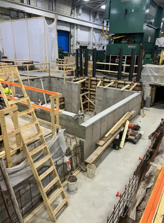
A large pit is dug roughly 20 feet into the ground to prepare for the press. Supporting walls are poured from cement within the hole and a connection is made to the existing underground scrap-removal conveyer (right side).
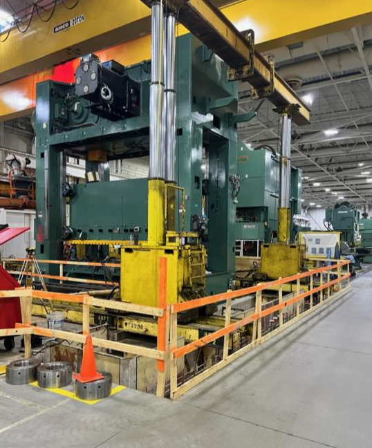
A gantry system is used to support the weight of the press as it is assembled and secured to the foundation.
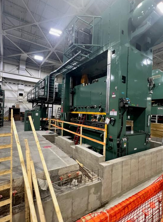
The press is assembled and secured in the pit. Capacitors are installed in the back.

Dog clutch without angular backlash
Gabriela Achtenova, Michal Jasný, Jiri Pakosta, Rômulo do Nascimento Rodrigues Center of Vehicles for Sustainable Mobility, Czech Technical University in Prague Dog clutches are cost-effective but often suffer from angular backlash, causing discomfort. A novel, patented design has been developed to eliminate this issue using a purely mechanical blocking mechanism. This design, fully interchangeable with […]
Continue reading
Dog clutch without angular backlash
Gabriela Achtenova, Michal Jasný, Jiri Pakosta, Rômulo do Nascimento Rodrigues
Center of Vehicles for Sustainable Mobility, Czech Technical University in Prague
Dog clutches are cost-effective but often suffer from angular backlash, causing discomfort. A novel, patented design has been developed to eliminate this issue using a purely mechanical blocking mechanism. This design, fully interchangeable with conventional mechanisms, requires no extra modifications but needs an external synchronization system.
Featuring innovative gearshift dogs and blocking mechanisms, it was tested with two prototypes on test benches. The results showed the design’s effectiveness, and robustness especially for hybrid and electric vehicles, addressing key shortcomings of traditional clutches.
Introduction
Greenhouse gases, CO2 regulations, alternative fuels, and vehicle electrification are critical issues driving the rapid growth of hybrid (HEV) and electric vehicles (EV) [1]. This shift demands innovative solutions in automotive engineering. This research focuses on developing a new gearshift mechanism to meet these demands. In HEVs and EVs, the electric motor can act as an external synchronization mechanism, potentially reducing costs. Parallel hybrids, requiring a wide range of gear ratios, benefit from cost-effective gearboxes like manual parallel shaft gearboxes (MT) or automated versions (AMT) [2][3]. These gearboxes commonly use synchronizers, a prevalent gearshift mechanism in passenger cars [4].
This research aims to replace the synchronizer with a new, cost-effective gearshift mechanism that eliminates the need for synchronization while maintaining or surpassing the synchronizer’s functions [5]. Typically, a dog clutch is the simplest gearshift mechanism for constant mesh gears but has been limited by driving comfort and NVH (Noise, Vibration, and Harshness) concerns. In electric powertrains, NVH issues include gear whine and gearshift mechanisms [4],[6]. Reducing angular backlash is crucial for minimizing NVH, a feature of the new mechanism, while ensuring cost-effectiveness and compactness. More compact gearboxes tend to be stiffer, further reducing NVH [7].
This research introduces a patented dog clutch design addressing angular backlash, a common issue in traditional mechanisms [7]. Using a purely mechanical blocking system, it minimizes backlash and improves shifting quality. The form of dogs enables very fast disengagement of the speed even under load. Rigorous prototype testing confirmed its functionality, durability, and comfort, making it suitable for vehicle gearboxes.
Final design of dog clutch with blockchain mechanism
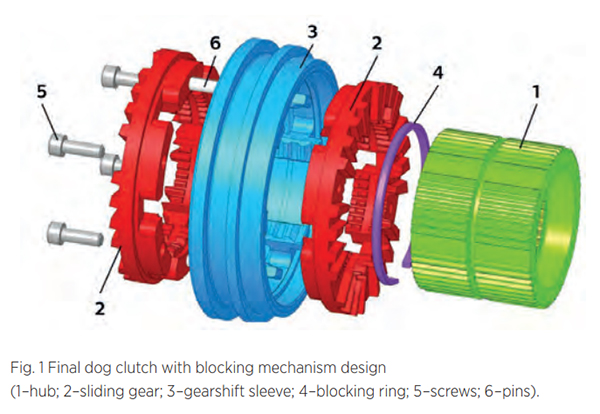
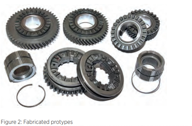
The clutch assembly (Figure 1) includes a hub (1) on the gearbox shaft, a sliding gear (2) that moves axially to engage gears, a gearshift sleeve (3) for controlling movement, and a blocking ring (4) to secure the sliding gear in positions. The sliding gear is split into two halves connected by screws (5) and pins (6). One blocking ring locks the sliding gear in all three positions (engaged/neutral/engaged) and secures the gearshift sleeve in neutral. No changes to the standard MT/AMT gear selector mechanism are needed. The design’s uniqueness is confirmed by Patent No. 307443[8] and the utility model „Schaltungskupplung“ [9]. Following design optimization, prototypes of dog clutches with a blocking mechanism were produced. Two clutches for the MQ200 gearbox were made to engage 1st, 2nd, 3rd, and 4th gears, see Figure 2. The prototype production was funded and supported by ŠKODA AUTO.
Gearshift process
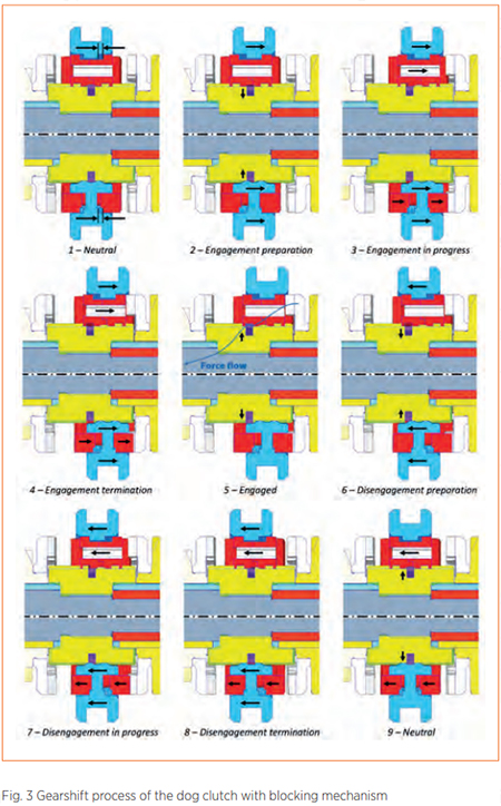 The blocking ring stays concentric with the hub due to its constant contact with the sliding gear or gearshift sleeve. With six contact points, the ring maintains its shape during compression. To prevent uneven deformation, which could interfere with gear movement and cause excessive wear, the ring’s ends are bent inward. Figure 3 illustrates the gearshift process, where shifting the right gear involves:
Position 1 – neutral:Black arrows show axial backlash between the sliding gear and the gearshift sleeve. The blocking ring holds both components – sliding gear (upper) and sleeve (lower) – in neutral;
Position 2 – engagement preparation:The sleeve moves right, compressing the blocking ring, while the sliding gear remains in neutral until backlash is resolved;
Position 3 – engagement in process:With backlash removed, the sleeve pushes the sliding gear right, and the blocking ring stays compressed;
Position 4 – engagement termination:The sliding gear reaches its maximum position, engaging the gearshift dogs. Both components stop moving axially, and the blocking ring is no longer compressed;
Position 5 – engaged: The blocking ring expands back to its original position, fitting into the sliding gear’s groove, preventing clutch disengagement due to torque;
Position 6 – disengagement preparation:The sleeve moves left to compress the blocking ring. Axial backlash is present, keeping the sliding gear engaged;
Position 7 – disengagement in progress:The blocking ring is fully compressed, backlash is gone. The sleeve moves the sliding gear to
Position 8 – Disengagement Termination: The sleeve reaches neutral, but the sliding gear remains slightly engaged due to kinetic energy. The decompressing blocking ring helps move the gear to neutral;
Position 9 – Neutral:The dog clutch returns to the neutral position, same as Position 1.
Prototypes of the clutch were designed for the MQ200 gearbox, where the blocking ring withstands axial forces up to 2 kN during dog engagement, transferring a maximum torque of 200 Nm. The force needed to engage and disengage the clutch via the gearshift sleeve is about 45 N, which is well within permissible limits and comparable to manual shifting forces. The sliding gear and gearshift sleeve have been optimized for powder metallurgy. For the sliding gear, only grooves for the blocking rings and threads on one half need machining, while the gearshift sleeve requires machining of the inner groove for the neutral position. The outer groove, for the gear selector fork, is for prototype compatibility and can be omitted in future designs. No additional parts are required between the sliding gear and gearshift sleeve, ensuring concentric alignment with the hub. The blocking ring is fixed securely and cannot rotate around the shaft axis due to the pin.
Verification of the dog clutch
The fulfillment of the requirements for the dog clutch with a blocking mechanism needed to be validated against the design specifications. First experiments were static to verify the shift force and unwanted disengagement. The resulting gearshift force required to compress the blocking ring was measured to be 45 N.
Further was experimentally tested that the blocking ring functions as intended, preventing unwanted disengagement of the clutch.
The dynamic tests were dedicated for verification of function and for endurance tests. The first phase of clutch prototype testing used an inertia test bench with the output shaft connected to a large inertia disc. Tests focused on smooth shift sleeve movement and proper engagement / disengagement of the dogs. No unexpected behavior was observed.
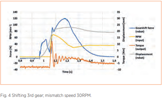
The gearbox was connected to the gearshift robot on the inertia test stand, and gearshifts were performed with various input parameters. Mismatch speed was controlled by the difference between the stationary input shaft and the rotating wheel or by gear ratios between two gears. Figure 4 shows data from a gearshift with 3rd gear engaged at a mismatch speed of 30 RPM. The gearshift process began at 0.96 s, with rising displacement and force curves. A sharp drop in force at 1.02 s indicated compression of the blocking ring, allowing the sliding gear to move. The force increased as the dogs engaged, and by 1.08 s, engagement was complete. The gearshift took about 60 ms.
To proceed with dynamic check of the blocking mechanism, the gearbox was moved to dynamometric test bench. The function for the 3rd and 4th gears were performed with positive result. Due to test bench capacity 1st and 2nd speed were not tested.
Service life (endurance) tests were conducted for the 3rd and 4th gear clutches on the inertia test bench, with each gear being shifted 180,000 times and the gearbox output set to 89 RPM. This low speed simulated a mismatch speed of around 140 RPM, optimizing the gearshift process and eliminating the need for external synchronization. Each shift took just over 2 seconds, resulting in 220 hours of continuous testing per clutch and blocking ring.
Conclusion
The new patented dog clutch with a blocking mechanism enhances efficiency and reduces costs for electric and hybrid vehicles. It offers minimal angular backlash (less than 0.1°) and can disengage under load, improving shifting comfort and torque transmission. This purely mechanical design is compatible with standard gear selectors, including sequential shifting, and requires no additional modifications. The clutch’s blocking ring withstands high axial forces, preventing unwanted disengagement. Prototypes, tested in a standard five-speed gearbox, demonstrated up to 30 mm axial space savings compared to conventional synchronizers. The design supports effective serial production using powder metallurgy and has proven durability with a service life of 700,000 cycles.
References
[1] PILLOT, Christophe. The Rechargeable Battery Market and Main Trends 2020-2030. Lyon: Avicenne Energy, 2022.
[2] HOFMANN, Peter. Hybridfahrzeuge – Ein alternatives Antriebssystem für die Zukunft. Switzerland : Springer, 2014. Second edition. ISBN: 978-3-7091-1780-4
[3] NAUNHEIMER, Harald et al. Automotive Transmissions: Fundamentals, Selection, Design and Application. Berlin : Springer-Verlag, 2011. ISBN 978-3-642-16216-8.
[4] FISCHER, Robert et al. The Automotive Transmission Book. Switzerland: Springer International Publishing, 2015. ISBN 978-3-319-05262-5.
[5] MEHRGOU, Mehdi et al. NVH Aspects of Electric Drives-Integration of Electric Machine, Gearbox and Inverter. 2018. SAE Technical Paper 2018-01-1556. doi: 10.4271/2018-011556. ISSN 0148-7191.
[6] Wu,G.,Zhang, X.,& Dong, Z. (2015). Powertrain architectures of electrified vehicles: Review, classification and comparison. Journal of the Franklin Institute, 352(2), 425–448. doi: 10.1016/j.jfranklin.2014.04.018
[7] TŮMA Jiří. Vehicle Gearbox Noise and Vibration. New Delhi: John Wiley & Sons, Ltd., 2014. ISBN 978-1-118-35941-9.
[8] ČESKÉ VYSOKÉ UČENÍ TECHNICKÉ V PRAZE, FAKULTA STROJNÍ. Řadící spojka. Inventors: JASNÝ, M., G. ACHTENOVÁ and J. PAKOSTA. File No. MPT F 16 D 11/10. Patent No. 307443. 22. August 2018. Czech Office of Industrial Property. Patent.
[9] SCHECHISCHE TECHNISCHE UNIVERSITÄT IN PRAG, FAKULTÄT FÜR MASCHINENBAU. Schaltungskupplung. Inventors: JASNÝ, M., G. ACHTENOVÁ and J. PAKOSTA. IPC-Class F16D 11/00 (2006.01). File No. DE: 20 2018 103 633.5. 26. June 2018. Deutsches Patent- und Markenamt. Utility model.
Driving sustainability – Reducing the embedded emissions of copper in electric vehicles
Bruno De Wachter, Independent Advisor, International Copper Association Since the publication of the EU Green Deal, e-mobility OEMs and Tier 1 suppliers in Europe have been actively seeking ways to evolve towards carbon neutrality. For such a journey to be successful, open communication across the entire value chain is essential. This article develops the case […]
Continue reading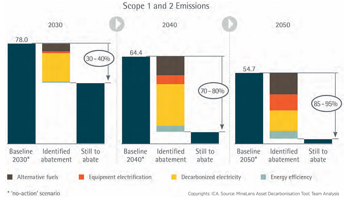
Driving sustainability – Reducing the embedded emissions of copper in electric vehicles
Bruno De Wachter, Independent Advisor, International Copper Association
Since the publication of the EU Green Deal, e-mobility OEMs and Tier 1 suppliers in Europe have been actively seeking ways to evolve towards carbon neutrality. For such a journey to be successful, open communication across the entire value chain is essential. This article develops the case for copper, a key raw material of the EV powertrain.
Copper in EVs – There is great potential to significantly reduce embedded GHG emissions associated with copper in the years to come.
Copper has the highest electrical conductivity of all non-precious metals, a quality put to good use in the stator windings of electric motors and induction motor rotors, as well as batteries, cabling and electrical connections. As OEMs and Tier 1 automotive industry suppliers develop their decarbonization plans, reducing copper’s embedded greenhouse gas (GHG) emissions is one of the challenges. A common approach to achieving this is by setting out a series of KPIs and milestones for their copper suppliers.
The good news is that there is certainly potential for reducing the carbon emissions from copper production to net-zero over the coming 30 years, and without the need for major technological breakthroughs. But for these conditions imposed by manufacturers in the automotive industry to be effective and actually help the copper industry speed up their decarbonization process, they have to be formulated in the right way, which requires some insight into the copper production process and material flows.
The copper production process and its emissions
A whole sequence of processing steps is required to produce high purity copper. The process of extracting primary copper from ores begins, of course, with mining, followed by concentration through a flotation process, and a first stage of refining in smelters using pyrometallurgical methods. The material is then subjected to a second stage of refining through electrolysis. An alternative route for low grade ore is the hydrometallurgical process, which separates the copper from the ore through leaching and then extracts it from the remaining solution through electrowinning.
Secondary copper is produced from scrap originating from manufacturing processes or end-of-life products. High purity scrap can be remelted directly with no need for refining, while less pure scrap requires additional processing. This can take place in dedicated secondary smelters, or the material can be added to the primary production process at various stages, depending on the scrap’s purity. This means that high-quality copper metal is often produced from a combination of primary and secondary sources.
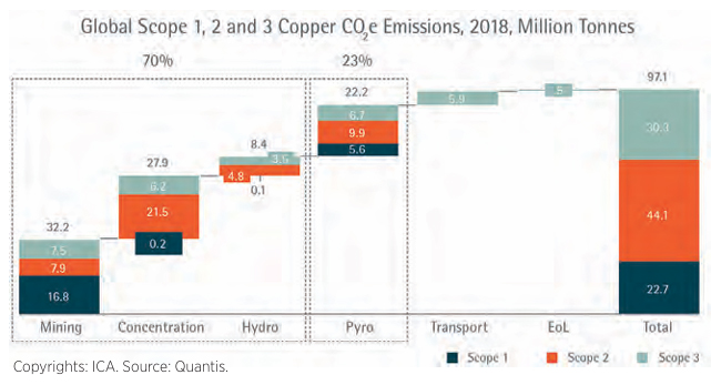
According to an analysis by the International Copper Association (ICA), copper production currently leads to a total of 97 million tonnes of GHG emissions annually, or 0.2% of total global emissions. Of these emissions, approximately 70% are generated by mining, 23% originate from smelting and refining, and the remaining 7% come from upstream and downstream transport and end-of-life treatment of products.
A major component of the GHG emissions associated with primary copper comes from electricity, from fossil fuels used in mining transport and equipment, and from fuels used in smelting furnaces at various stages of the production process. The GHG emissions of secondary copper depend on the purity of the scrap, since this determines at what stage in the refining process it is added, but they are generally lower than those from primary copper. That said, using secondary copper can never be the sole and complete solution to decarbonization, as explained later. For this reason, reducing the impact of the primary production routes should receive major focus in the decarbonization process.
The pathway to net-zero
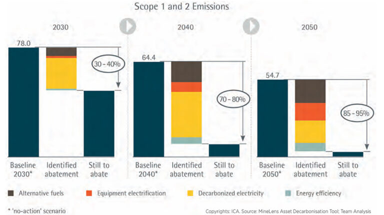
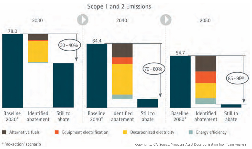
The decarbonization of the copper production process has already started, with numerous initiatives by individual companies involved in copper mining and refining. To step up the momentum, the ICA with its members developed a path forward to bring the carbon foot print of copper production as close as possible to net zero by 2050 (’Copper – The Pathway to Net Zero’). Made public in March 2023, the Pathway sets out a pragmatic approach to decarbonizing copper production, using existing technologies. It delineates which decarbonization options can be activated, by when, and with what impact. It also outlines some enabling conditions that should be in place to achieve this.
For scope 1 and scope 2 emissions, the Pathway identifies four major types of levers. The first is equipment electrification, to include the haulage trucks used in mining. An example of good practice is demonstrated by Boliden, a Swedish mining company which introduced electric trolley assistance in its haulage trucks in 2018, saving significant amounts of diesel fuel (Boliden, 2018). At the same time, underground mining machinery is being electrified at a rapid pace, coming with the additional benefit of saving the energy and cost of ventilation. The second lever is decarbonizing the electricity supply. This includes switching from standard to green electricity, alongside the option of installing wind and solar energy farms at copper production sites. A third lever is replacing fossil fuels with biofuel, biogas, or green hydrogen, particularly in smelting furnaces. A fine example of this is at German copper producer Aurubis, which has started using hydrogen instead of natural gas for the reduction process in its anode furnaces – an innovation set to reduce GHG emissions by around 5,000 tonnes each year (Aurubis, 2023). The fourth major lever encompasses various kinds of energy efficiency improvements at various stages of the production process. In a collective commitment, ICA members declared that they will be applying these and other measures to reduce their scope 1 and 2 emissions by 30 to 40% by 2030, 70 to 80% by 2040, and 85 to 95% by 2050.
A similar approach has been followed for scope 3 emissions, subject to the proviso that the results for this category depend on all the actors in the value chain collaborating. ICA members aim to reduce these emissions as far as possible by 2050, and will do what they can to unite every stakeholder behind this goal.
Recycling and decarbonization
Copper’s infinite recyclability is a major advantage. About 80 percent of copper is used in an unalloyed form, making the recycling process more straightforward. Even for copper that is alloyed or contains other materials, recycling can still be achieved without downgrading. Unwanted elements can be efficiently removed to recover the copper in its pure state, ready to be re-used in any kind of application. Because of its high degree of recyclability, copper already in use in its various applications is not regarded as lost, but can instead be legitimately considered part of the world’s copper reserve, often referred to as society’s „urban mine”.
Its high level of recyclability, combined with the fact that copper from secondary sources produces fewer GHG emissions than primary sourced copper, could lead to the simplistic conclusion that increasing the share of secondary material would be a good strategy for reducing embedded emissions. While this solution will work at individual plant level, it does not make sense on a European or world wide scale. Due to the long average lifetime of products using copper (typically 25 to 30 years) and strong growth in copper demand (practically doubling every 30 years), the availability of end-of-life material is far too limited to meet the demand for new material. Additionally, no process is 100% efficient, and there will always be losses associated with collecting, separating, and re-processing copper scrap.
Note that a distinction should be made between fabrication scrap, which originates from the production of end-use material out of semi-finished goods, and end-of-life scrap, which originates from end-of-life products.
Globally, scrap recycling rates from end-of-life products averaged around just 15% over the period from 2000 to 2020. Estimating future recycling rates is complicated by various uncertainties, but MineSpans by McKinsey expects the end-of-life recycling input rate to increase to 23 percent over the next 30 years.
Fabrication scrap contributed to about 16% of semi-finished goods production globally, a figure expected to remain stable. Bearing this in mind, any requirement set by raw material purchasers to increase the total recycled content of new copper above 35%-40% can only result in less recycled material being used elsewhere, leading to zero net reduction in GHG emissions at global level.
Moreover, the main levers for increasing recycling rates are in the collection and separation of end-of-life material, and consequently not in the hands of copper producing companies. Design engineers at every level of the automotive industry can play their role by favouring product designs that facilitate dismantling and separation at end-of-life (“design for recycling”). In some cases, collaborations between various stakeholders and the copper industry to capture and process the cleanest scrap and create a closed loop can set a good example. Recycling rates could also benefit from incentives for end-of-life collection, from staff upskilling for end-of-life management, and from improved separation techniques for treating multi metal scrap streams. Improved systems for car registration and waste stream reporting could avoid end-of-life vehicles being exported from the EU or going under the radar in other ways.
Collaboration across the value chain
All this considered, e-mobility OEMs and Tier 1 suppliers should not be over-concerned about the feasibility of reducing the embedded GHG emissions of copper conductors. The ICA and its members have developed a decarbonization pathway for the next 30 years based on existing technologies and that will bring the carbon footprint of copper production as close as possible to net zero by 2050. But to unlock its full potential, the pathway depends on stakeholder across the value chain communicating and collaborating with each other, upstream from copper production as well as downstream.
Purchase managers from the automotive industry can work with their copper suppliers to develop a roadmap to reduce embedded emissions and offer collaboration avenues to accelerate the process.
Raw material sourcing managers responsible for purchasing copper products should be aware of the limits of using recycled content as a means of reducing embedded GHG emissions. At the same time, they could consider developing closed loop business models for copper used in the automotive industry. Design engineers can play their role in this process by facilitating dismantling and separation at end-of-life.
With this level of collaboration across the entire value chain – stake holders communicating and interacting and achieving what is within their reach – there is great potential to significantly reduce embedded GHG emissions associated with copper in the years to come, while improving the collection and recovery rates of copper in end-of-life vehicles.