
DRIVING TOMORROW −
POWERTRAIN & MOBILITY REDEFINED
International Congress and Expo | 8 – 9 December 2026, Estrel Hotel, Berlin & Digital
An event by
THE PREMIER INTERNATIONAL EVENT FOR THE FUTURE OF DRIVETRAINS AND MOBILITY
Decarbonisation, electrification, and digitalisation are transforming the mobility industry. But it’s not just technology that’s driving change – regulatory uncertainty, shifting policy frameworks, and geopolitical dynamics are redefining how we innovate, invest, and collaborate. Navigating this transformation requires open dialogue, cross-sector collaboration, and cutting-edge engineering. At the CTI Symposium Berlin, over 650 top-level experts and decision-makers from OEMs, Tier 1 suppliers, technology companies, research institutions, and government bodies come together to explore the latest developments in electrified drivetrains, hybrid solutions, energy systems, software integration, and mobility strategies.
Speakers 2025


14 DEEP DIVE SESSIONS
80+ EXPERT LECTURES
25h CONTENT & NETWORKING
70+ EXHIBITORS
650+ INDUSTRY REPRESENTATIVES
START-UP AREA
EXPO STAGE
WHY CTI SYMPOSIUM BERLIN?
The CTI Symposium is neutral, international, and insight-driven. It is not guided by any corporate or political agenda – but by the shared commitment to innovation, technical excellence, and open exchange across the global powertrain community. This is where strategy meets technology, and where today’s challenges turn into tomorrow’s solutions. Be part of the dialogue. Make connections. Lead the change.
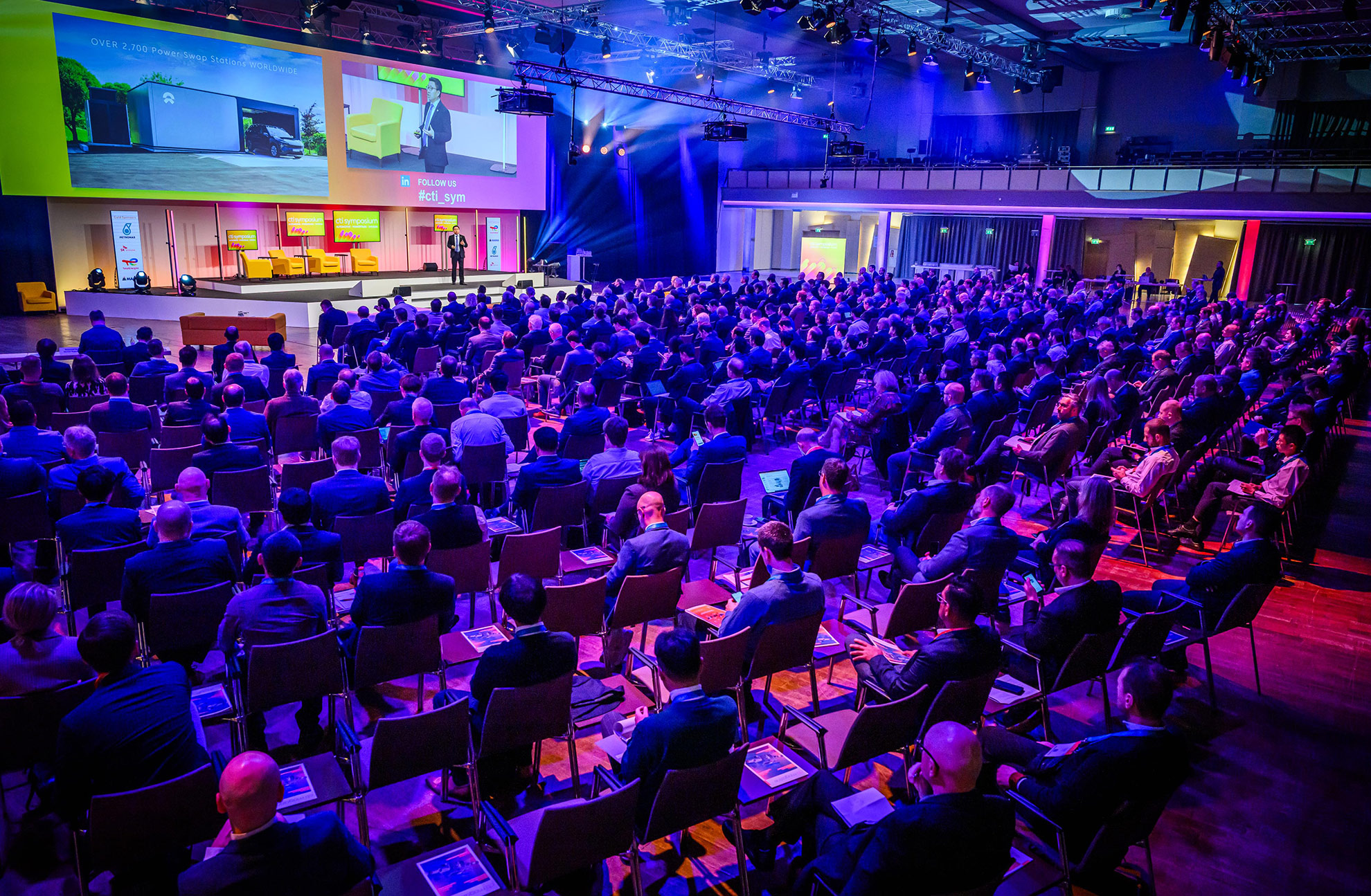
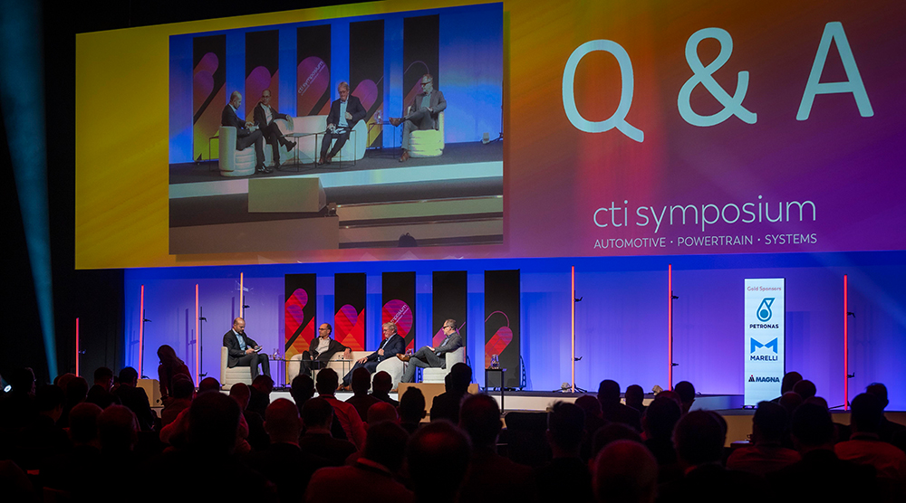
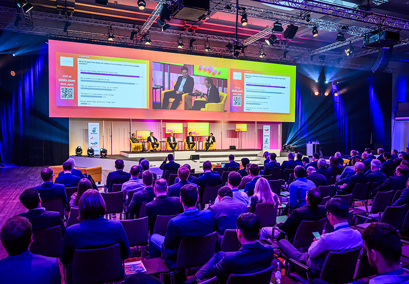
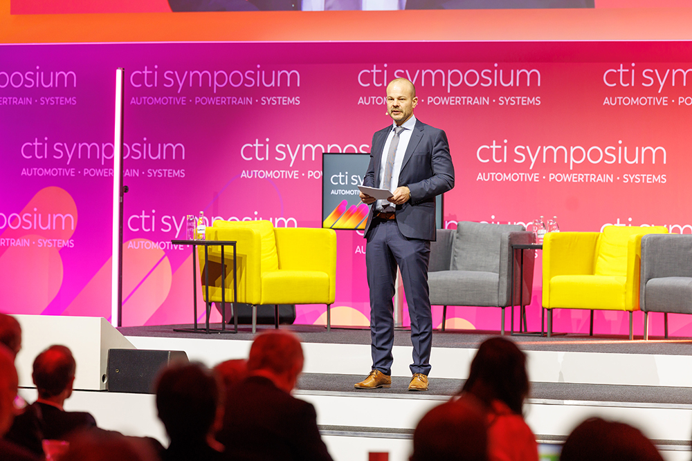
Impressions 2025

Follow us on LinkedIn
Updates from cti-symposium.world

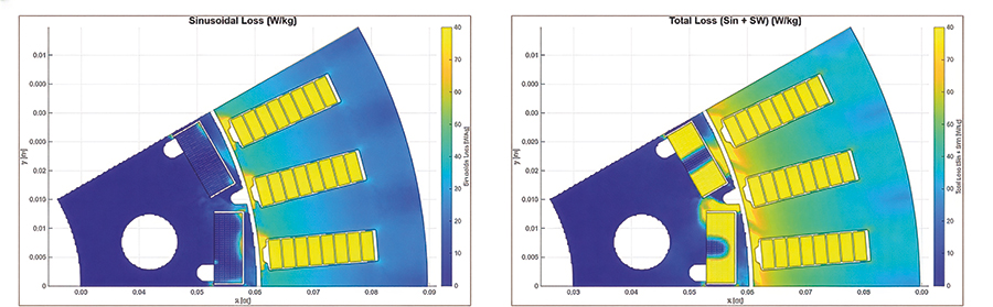
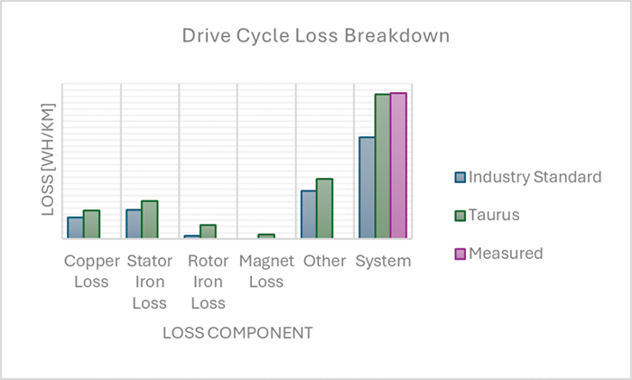
Taurus: a powerful mix of industry standard and lessons learned through experience
Automotive drivetrain engineers aim to perfect and refine electric drive lines to the point where they operate right at the edge of what is physically possible. This requires simulation models, to act as cost function in the design process or to train reduced order models. These latter models should incorporate all physical loss and performance […]
Continue reading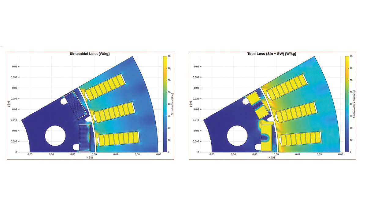
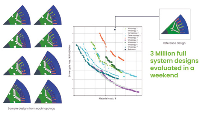
How deeptech is already revolutionising EV powertrain engineering
Simon Shepherd, Head of eDrive and Chief Product Officer, Monumo Deeptech is transforming EV powertrain engineering by introducing new levels of computational freedom, speed, and system integration, allowing companies to achieve levels of performance and cost reduction previously out of reach through existing methods.
Continue reading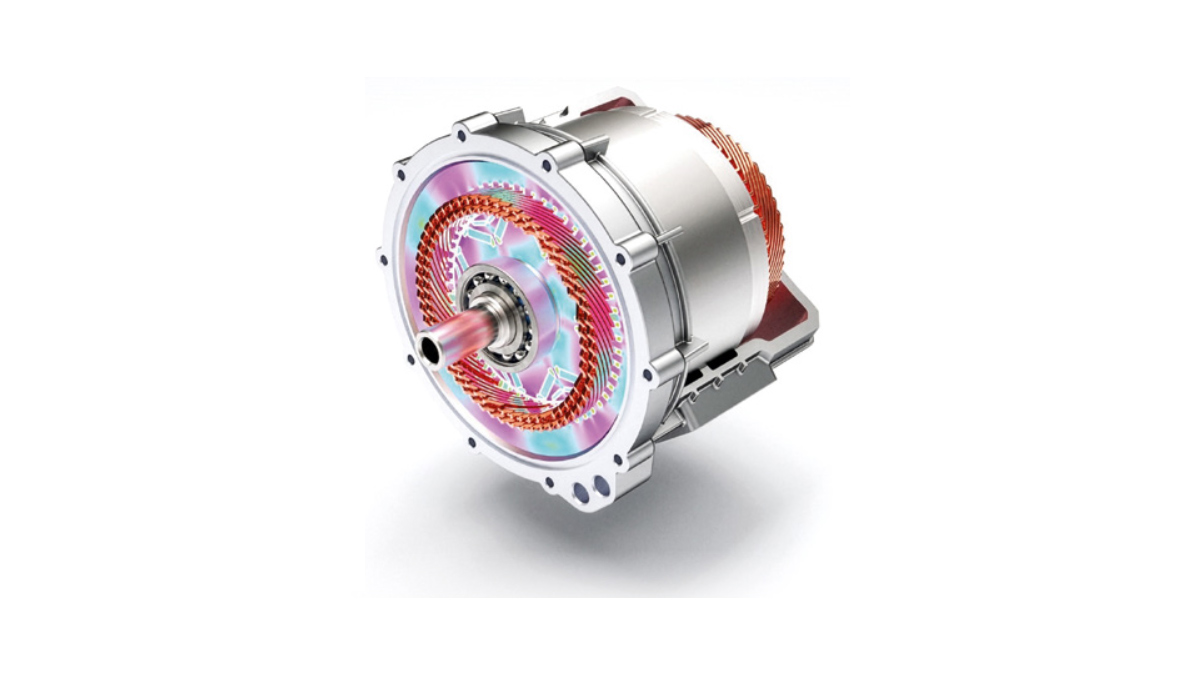
AI-Powered Engineering Software for Electric Drives: OPED
Boosting powertrain development with agility, fast time-to-market and optimal product-market fit Dr. Martin Hofstetter, Head of E-Mobility and Alternative Drivetrains Research Group, Graz University of Technology Dr. Dominik Lechleitner, Senior Researcher, Graz University of Technology Designing electric powertrains is challenging: engineers must quickly find competitive designs and optimize the system for multiple key performance indicators […]
Continue reading
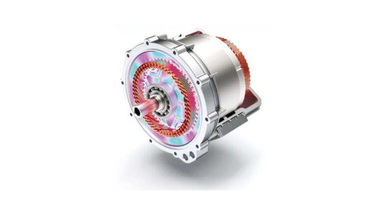
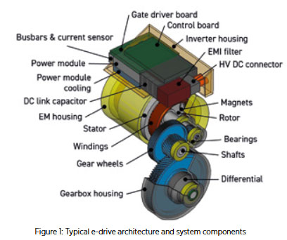 The development of electric drives (e-drives) is a highly complex and interdisciplinary process. Engineers must simultaneously design numerous electrical and mechanical subsystems (see Figure 1) that must optimally work together while meeting ambitious system targets for performance, efficiency, cost, and packaging. These objectives are often conflicting – improving one typically worsens another. Moreover, this highly challenging task must be solved under strong time pressure as it is critical for ambitious time-to-market goals. Therefore, engineering of electric drives demands digital tools capable of handling multi-criteria optimization and cross-domain interactions in an integrated way to quickly provide solid answers to complex questions.
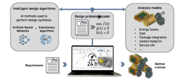
CTI Symposium USA
19&20 May 2026, Novi, MI, USA