Philippe Pauchard, Application Engineer at DuPont (Switzerland)
Christoph Berger, Application Development Manager, DuPont (Germany)
Electric erosion in bearings
Undesirable parasitic electrical currents in traction motors can pass through roller bearings and cause damage known as electrical erosion. This phenomenon is characterized by electrical discharges between the rolling elements and the bearing raceways, leading to the formation of spot welds at the contact surfaces. During operation, these spot welds repeatedly break apart, generating abrasive metal debris that accelerates wear and can result in premature bearing failure.
Electrical erosion can affect bearings in various types of electric motors, including AC, DC, servo, and stepper motors, and is most observed in
high-speed motors, electric vehicle regenerative braking systems, and motors controlled by variable frequency drives (VFDs). In severe cases,
electrical erosion can lead to premature motor failure, posing safety risks, increasing downtime, and resulting in significant repair and replacement costs.
Common solution
A common mechanical solution to prevent electrical erosion is the use of hybrid ball bearings with ceramic rolling elements. These bearings provide electrical insulation between the rotor and the housing, thereby eliminating the conductive path required for electrical discharge and subsequent erosion. However, it is important to note that hybrid ceramic ball bearings can be more expensive than standard steel bearings. For roller bearings, or for bearings designed to carry higher loads and therefore employing larger rolling elements, hybrid solutions are either significantly more costly or not commercially available.
A more economical approach is to electrically insulate standard steel bearings. Ceramic-coated bearings, typically using aluminum-oxide coatings applied to the inner or outer ring, effectively block DC and low-frequency stray currents. Coating thicknesses in the range of approximately 100–200 μm are commonly rated for 1–3 kV DC breakdown voltage. However, due to their capacitive behavior and limited mechanical robustness, such coatings may provide reduced protection against high-frequency electrical discharge in modern motors controlled by variable frequency drives (VFDs).
Insulating Sleeve Idea
To effectively protect against high-frequency electrical discharge and avoid capacitive effects, a thicker electrical insulation barrier is required.
Polymeric insulating sleeves, typically with thicknesses in the range of 1 to 2 mm, can be used for this purpose. The choice of polymer, however,
is constrained by its dimensional stability at the peak operating temperature of the application. For EV traction motors, peak temperatures typically specified by OEMs are around 150 °C. While many polymers do not melt until higher temperatures, they often exhibit a glass transition temperature below 150 °C, which compromises dimensional stability at elevated operating temperatures.
The use of glass-fiber reinforcement can help mitigate this effect and increase temperature capability; however, the presence of glass fibers may
introduce abrasive wear on metallic counter surfaces, such as aluminum housings. To address these limitations, a high-temperature polymer is required that maintains dimensional stability at elevated temperatures without the need for fiber reinforcement.
Vespel® polyimide: Balancing electrical insulation and dimensional stability
Vespel® S is a sintered polyimide that exhibits no observable glass transition temperature or melting point. Its exceptional high-temperature resistance allows it to be used as an insert in die-cast aluminum components. This unique property is particularly important for applications involving high mechanical loads and elevated temperatures, such as traction motors operating in critical drive modes or under malfunction conditions.
Vespel® polyimide insulating bearing sleeves can be used to electrically insulate the rotor from the housing, thereby suppressing discharge currents. They provide a versatile and cost-effective solution for mitigating electrical corrosion in electric motor bearings and can be installed during final assembly by press-fitting standard ball bearings. A Vespel® polyimide insulating layer with a thickness between 1 and 2 mm offers robust electrical insulation by significantly increasing electrical impedance. This effectively attenuates high-frequency currents traversing the bearing, thereby reducing the risk of electrical erosion. In addition, Vespel® polyimide exhibits mechanical damping properties that may help reduce noise, vibration, and harshness (NVH) in electric motor systems.
Manufacturing Vespel® bearing Sleeve
Vespel® polyimide components are manufactured using a powder-based direct forming process followed by high-temperature sintering. In this process, polyimide powder is compacted at room temperature into a green part, which is then sintered to produce a dense, non-meltable polyimide component. Unlike injection-molded parts, sintered components do not exhibit structural weaknesses such as weld lines or injection points. Depending on the final tolerances required for the assembly, the sintered parts can be machined using conventional metalworking equipment, including grinding operations, enabling the production of high-precision finished components.
Assembly of Vespel® sleeve onto the bearing
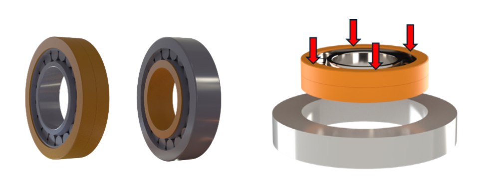
The Vespel® sleeves can be installed by press-fitting them onto either the rotor shaft or one of the bearing rings (Figure 1). In all configurations, standard steel ball bearings can be used in combination with the Vespel® sleeve, thereby eliminating the need for costly ceramic rolling elements such as those used in hybrid bearings.
Figure 1: Vespel® bearing insulation sleeves can be installed on the outer diameter (left) or on the inner diameter of the bearing (right)
Figure 2: Assembly of bearing has been done on a 88 mm diameter roller bearing (NU209)
Assemble Bearing Equipped with Vespel® Sleeve
The assembly of bearings equipped with a Vespel® sleeve was evaluated by Durkopp, a manufacturer of roller bearings. In this study, Durkopp ground the outer diameter of several test bearings to achieve press-fit conditions ranging from +5 μm clearance to 50 μm interference. During assembly (Figure 2), the press-in force was measured using a load cell.
The maximum insertion force measured during assembly is shown in Figure 3 for various interferences. An assembly force of up to 9,300 N was recorded at the highest interference fit, with no observable damage to the Vespel® sleeve.
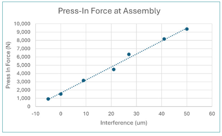
Figure 3: Maximum insertion force measured during assembly for various interference
Electrical Properties Comparison with Ceramic Bearing
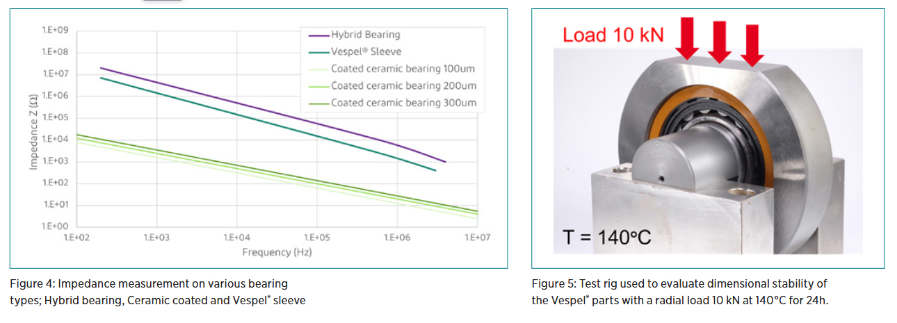
Various tests have been conducted to support the use of Vespel® sleeves in addressing electrical corrosion issues. The electrical impedance was measured by IMKT (Institut für Maschinenkonstruktion und Tribologie at Leibniz Universität Hannover). The results indicate that the electrical insulation performance of Vespel® SP-1, while slightly lower than that of hybrid bearings, remains within the same order of magnitude and is
significantly higher than that of ceramic-coated bearing solutions, even when compared with the thickest ceramic coating layer (Figure 4).
Static and Dynamic Load Testing
To demonstrate the mechanical resistance of the Vespel® sleeve, a test was conducted on an 88 mm-diameter roller bearing (NU209). A radial load of 10 kN, which is significant for a standard roller bearing, was applied for 24 hours at a temperature of 140 °C (Figure 5). The circularity
of the Vespel® sleeve outer diameter was measured before and after the test. The results indicate that the circularity increased only from 3.7 μm
to 5.2 μm, remaining well below the supplier’s specified limit of 9 μm for the bearing. These results demonstrate the excellent dimensional stability and mechanical resistance of Vespel® components under demanding operating conditions.
A similar test was conducted at a rotational speed of 3,000 rpm. In this case, the test was performed under a higher radial load of 25 kN, but at room temperature. The results indicate that the circularity increased only from 2.9 μm to 7.0 μm after the test, which remains below the supplier’s specified limit of 9 μm.
Summary
Electrical erosion is a major reliability concern in modern electric motors, particularly in high speed and VFD controlled applications where high frequency discharge currents accelerate bearing degradation. Conventional mitigation solutions such as hybrid ceramic bearings and ceramic coated bearings offer partial protection but are often constrained by high cost, limited availability, or reduced effectiveness under high frequency electrical stress.
The results presented in this study demonstrate that Vespel® polyimide insulating sleeves provide an effective and economical alternative for
electrically insulating standard rolling bearings. By introducing a thick polymeric insulation layer, Vespel® sleeves significantly increase electrical impedance, thereby attenuating high frequency discharge currents and reducing the risk of electrical erosion. Electrical testing confirms insulation performance comparable in magnitude to hybrid bearings and clearly superior to ceramic coated solutions.
Mechanical testing under representative load, speed, and temperature conditions further confirms the excellent dimensional stability and mechanical resistance of Vespel® sleeves. Their compatibility with standard bearings and conventional press fit assembly processes makes this solution particularly attractive for scalable industrial and automotive applications. Overall, Vespel® insulating sleeves offer a robust, versatile, and
cost-effective approach to improving bearing durability in electric motor systems.
© 2026 DuPont. All rights reserved. DuPont™, the DuPont Oval Logo, and all trademarks and service marks denoted with ™, ℠ or ® are owned by affiliates of DuPont de Nemours,Inc. unless otherwise noted. DuPont believes this information to be reliable. It may be subject to change as additional knowledge and experience are gained. It is not intended as a substitute for any testing you may conduct to determine for yourself the suitability of our products and information for your particular purpose. Since conditions for use are outside the DuPont’s control, DUPONT DE NEMOURS, INC. AND ITS AFFILIATES MAKE NO WARRANTIES, EXPRESSED OR IMPLIED, INCLUDING BUT NOT LIMITED TO WARRANTIES OF MERCHANTABILITY OR FITNESS FOR A PARTICULAR PURPOSE AND ASSUMES NO LIABILITY IN CONNECTION WITH ANY USE OF THIS PRODUCT AND INFORMATION. This information is not intended as a license to operate under or a recommendation to infringe any trademark, patent or technical information of DuPont or other persons covering any material or its use.