TREMEC is one of the major players in the aftermarket powertrain business with several generations of manual gearboxes known for their performance and robustness. To continue this tradition, the challenge of developing an electric drive unit (EDU) for aftermarket use was undertaken. The goal was to develop an EDU (named TR-DC6000) with a peak power output of 600kW that would fit many existing chassis, allowing it to be retro fitted in an existing internal combustion (ICE) vehicle converting it to electric drive or to upgrade the performance of existing electric vehicles. This paper will first contain an overview of the development history of this EDU to date together with the current state of the program. The main body will cover the relevant test results from our prototypes and how those were used to define the production design. The key differences between the prototypes (ED), and the production ready (DV) units will be explained. Finally, an outlook is provided on what the expected performance is for different use cases of this EDU.
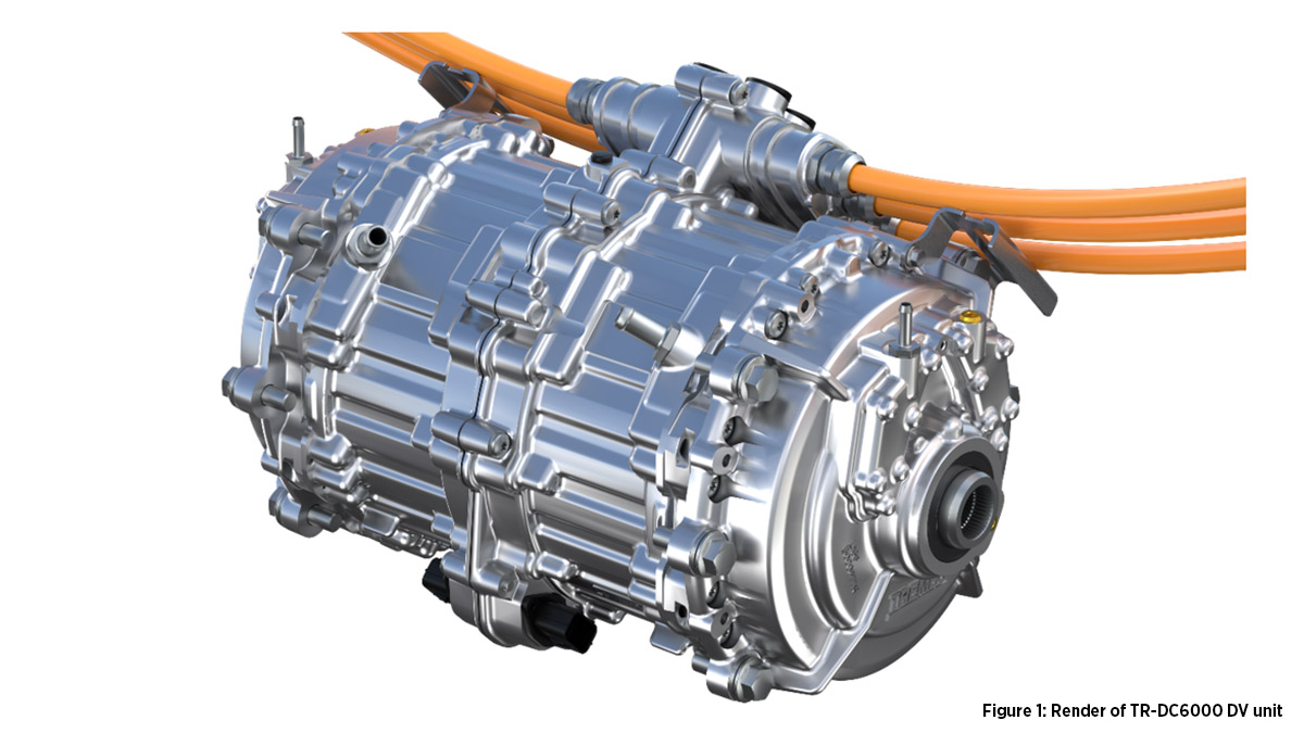
The selected configuration for the TR-DC6000 is a dual-motor concentric lay-out suited for 800V applications. The two electric motors are placed in the middle and each connect to a planetary gearbox providing the reduction to the wheels, see Figure 1. In order to easily fit in existing chassis, the inverters are connected through phase cables allowing some flexibility in their placement. The motors are surface-mounted permanent magnet (SMPM) machines with a carbon wrap or sleeve. Each motor can deliver up to 300 kW and spin up to 18.000 rpm. The inverters selected use 800V Silicon-Carbide (SiC) power modules to unlock the full potential and efficiency of the 8 pole-pair motors. Both the inverter and motor are water-cooled for ease of integration in existing vehicle coolant loops. The gearbox is passively lubricated and cooled with the use of several oil catchers, diverters, and scoops to ensure all components are well lubricated and remain within their operating temperature range.
In the past year, six prototypes have been built and continue to be extensively tested in the TREMEC lab on a dyno capable of the full torque and speed range. Three of the six units were subsequently installed in vehicles for integration testing, demo drives and performance evaluation. One of which, our in-house EV converted Porsche 996, is also used as a development platform for drivability and torque vectoring. Several more functional tests have been run to characterize the unit and compare with the design predictions, such as: thermal behavior, NVH and efficiency. A shortened durability test has been run to prove the robustness of the design, and a series of safety cases (including load dump) have also been completed.
One of the first major observations during the testing campaign was the sensitivity of the phase cable shield contacts at motor and inverter end. Several of these shield contact points showed signs of overheating. A series of specialized measurements and electrical simulations confirmed this was due to the induced AC current running in the phase cable shield as described in Frei et al1. The high electrical frequency of the motor, phase cable length and high current in the core during track diving caused the current rating of the original shield contact to be exceeded. Furthermore, the high shield current caused the phase cable itself to heat up over longer drive cycles outside of the nominal operating range. To thoroughly investigate and address the issue, a model was built that included the electrical coupling between the core and the shield of the phase cable, as well as the thermal behavior of the phase cable (thermal behavior modelled similar to the method described in Luttenberger2). This model, which allowed for simulating dynamic drive cycles, correlated well with the measurements without the need for parameter tuning (only physical parameters are used). Armed with this new tool, various design solutions were explored which resulted in a different phase cable / connector combination which would meet our durability and peak performance requirements – both electrically and thermally. The selected design, as well as an alternative solution where one common shield is placed around 3 unshielded phase cables, were then tested on our dyno, where the component temperatures were confirmed within margin even during track driving, see Figure 2 showing several data traces recorded on our dyno. The data shown is from a simulated Nürburgring lap where an average EDU power >300 kW is achieved. All critical component temperatures (stator, rotor and phase cables) remain well within their respective limits.
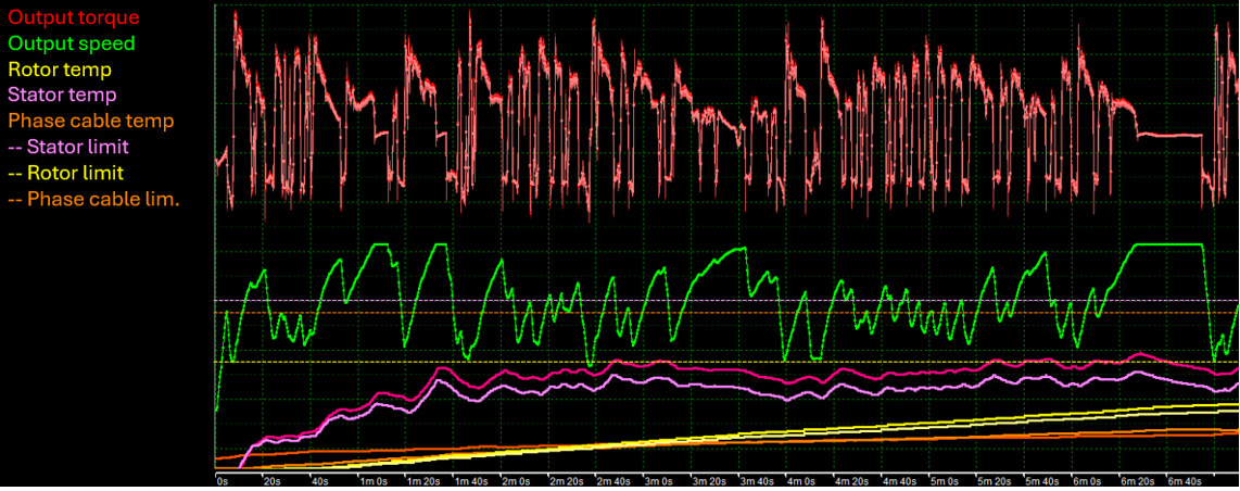
Figure 2: Data traces from Nürburgring lap on dyno with average >300kW power and thermal behavior well within limits
A second notable change to prepare the TR-DC6000 for production can be seen in the gearbox design. The prototypes utilized a stepped planetary gearbox to achieve a total ratio of 9.4. Upon reviewing manufacturability during the procurement phase, we encountered challenges with the initial concept, particularly given the low production volumes targeted for this product. Manufacturing stepped planet gears in small quantities proved to be either costly due to high tooling expenses that could not be offset by larger volumes, or overly complex, involving a welding step to join two simpler gears. In response, we shifted toward a design incorporating a single-stage planetary gearbox, while maintaining the same packaging space. This adjustment resulted in a lower gearbox ratio of 7.0, which lowered output torque, yet allowed for significant cost savings. These savings enabled us to enhance the motor with higher-grade magnets, partially compensating for the reduced torque. As a result, we still surpassed our targeted output torque of 6000 Nm. The alteration in design minimally impacted performance, adding only 0.25 seconds to the quarter-mile run, while notably improving efficiency. Specifically, efficiency increased by 3% over the Worldwide Harmonized Light Vehicles Test Procedure (WLTP) and by 9.3% during track driving, attributed to the generally lower motor speed.
While redesigning the gearbox to a single step lay-out some attention was also given to the ring gear fixation to the housing. Both the ED and DV designs use a splined connection. As this is an interface between a hardened steel gear and a softer aluminum housing, some wear or polishing is always expected. Under uniform loading the contact pressure in the spline is extremely low and would not raise any concerns, however due to the planet gear loads the ring gear deforms to a more triangular shape (see Figure 3). This results in a cyclic load pattern where higher contact pressures are expected and some movement takes place on the interface, causing wear. The limited durability testing confirmed some wear in this area. Though the wear was not at an alarming level, the opportunity was taken to mitigate risk. To minimize the wear, the approach was to both reduce the contact pressure and the movement, which was most easily achieved by increasing the ring gear stiffness (see Figure 3). In addition to increasing the ring gear stiffness, several other smaller optimizations to the housing and spline geometry were included in the new design. A full FEA model was created of the gearbox and housing interface to simulate the cyclic loads from the planet gears, deformation of all components, and the movement. The combination of contact pressure and movement, called work, could then be evaluated. The updated design results in 2.4 times lower work on this critical interface compared to the ED design, which will greatly improve the robustness of the EDU.
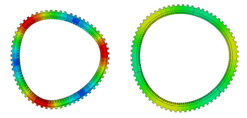
Figure 3: difference in ring gear deformation under equal output load: left ED, right DV
The changes listed above combined with multiple other tweaks to improve robustness, manufacturability or performance have prepared the TR-DC6000 design for low volume production. We have reliably demonstrated 0-100 km/h below 3s with our own test vehicle and projected times close to 2.5s with improved traction control. While running track drive cycles on our dyno we were able to run a lap of the Nürburgring with an average EDU power of >300kW resulting in a simulated lap-time below 7:45 for a 2000kg vehicle (see Figure 2). This combination of performance, robustness and flexibility makes this an ideal product for aftermarket EV projects and low volume niche car builders alike.
The first DV units with all their improvements are targeted to be built during Q4 2024, and a complete validation and industrialization plan is scheduled during 2025. Low volume production should then begin early 2026.
References:
- Frei, A. Mushtaq, K. Hermes and R. Nowak, “Current distribution in shielded cable-connector systems for power transmission in electric vehicles,” 2018 IEEE International Symposium on Electromagnetic Compatibility and 2018 IEEE Asia-Pacific Symposium on Electromagnetic Compatibility (EMC/APEMC), Suntec City, Singapore, 2018, pp. 881-886, doi: 10.1109/ISEMC.2018.8393908.
- Luttenberger, F., MSc. (2016). Electric components in automotive battery systems above 800 V (By Graz University of Technology, Institute of Automotive Engineering & AVL List GmbH).