Craig Renneker, Vice President Innovation, AAM
While the EV growth rate remains uncertain, there is little doubt that the use of automotive electric drive units must drastically increase to meet global climate objectives. This requires mass market acceptance across the full range of vehicles − size and price. A major enabler to reaching more customers is to reduce the cost, size and mass of Electric Drive Units (EDUs), as well as the quantity of natural resources required in manufacturing.
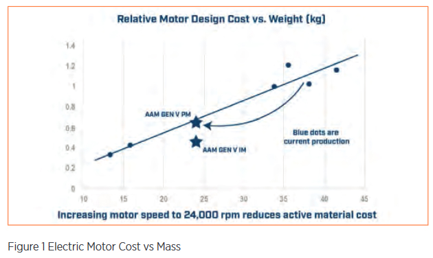
The power produced by an EDU is a product of its torque and rotational speed. Increasing the rotational speed enables power to be achieved at a lower torque. Simply put, spinning the motor faster reduces its size, mass and cost (Figure 1). The result: fewer costly materials are required, such as copper windings, magnetic steel and, in some cases, rare-earth magnets.
Traditional electric motors rarely spin to 20,000 rpm. Exceeding this level requires careful motor, gearbox and inverter design. This article discusses the approach AAM is taking to overcome various design obstacles to enable speeds up to 30,000 rpm – the speed needed to make a real impact in clean mobility and customer acceptance of EVs.
The Integrated Approach
An accessible EDU with a 30,000 rpm motor requires an integrated motor, gearbox and inverter. Each area presents specific challenges to execution and opportunities for new designs:
- Motor: pole count, rotor centrifugal forces, cooling, sealing and bearings
- Gearbox: pitch line velocity of the gear teeth
- Inverter: Switching losses
The Motor
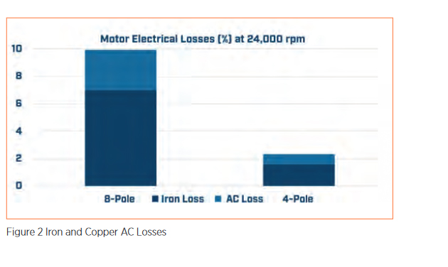
Most electric motors employ stators with 3-phase copper windings driven by sinusoidal alternating current. As the frequency of these sinusoidal currents increase, parasitic power losses in both the magnetic steel laminations and copper conductors increases. These are commonly called iron and copper AC losses. The required frequency for a 3-phase motor is determined by the motor pole count and rotational speed. Most motors today are 8-pole designs with interior permanent magnets. AAM uses a 4-pole architecture which requires half the sinusoidal current frequency of an 8-pole design. This significantly reduces iron and copper AC losses. (Figure 2)
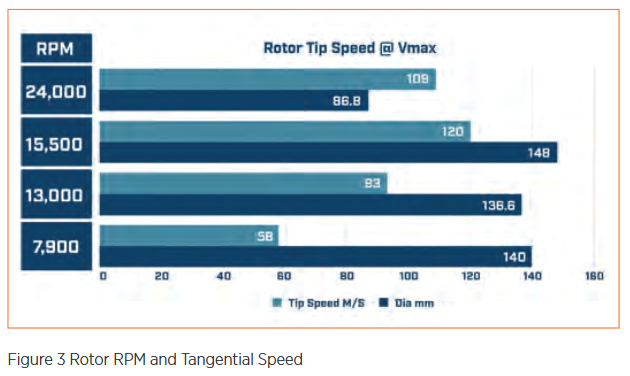
Reducing the diameter of the rotor enables higher speeds. Fortunately, higher-speed motors require less torque for a given power level, allowing a smaller diameter. As an example, the tangential speed of an 87 mm OD rotor at 24,000 rpm is lower than a much larger rotor spinning at 15,000 rpm (Figure 3). Using stress analysis of the lamination and magnet geometry, high speeds can be attained.
Smaller, fast turning motors have basic geometric challenges in removing heat. To effectively remove this heat AAM uses forced oil cooling of both the stator and rotor. A series of stamped holes in the stator laminations are arranged to form helical cooling passages around the copper windings. Oil is also pumped into the hollow rotor shaft with special heat sink features to increase surface cooling. This method reduces the heat generated in both the stator and rotor without the need for a glycol-cooled motor jacket.
AAM is employing a completely different approach to cooling highspeed rotors. Instead of pumping glycol coolant through the hollow center of the rotor requiring radial lip seals, AAM is cooling the stator, rotor and inverter with the same low-viscosity oil used to lubricate the gears and bearings. With this arrangement, no sealing is required between the rotor and gearbox elements.
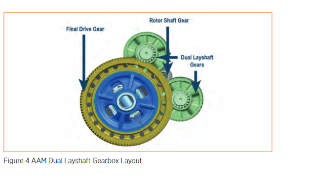
In most EDUs, a simple 2-stage helical-gear reduction is used to step motor speed down to the vehicle wheel speed. The pressure angle of the gear teeth generates a radial load proportional to gear torque that must be carried by bearings on the rotor axis. With a typical singlemesh, 2-stage helical gear reduction, bearing capability limits motor speeds to 20,000 rpm. AAM uses a dual-layshaft gearbox arrangement to balance these gear separation loads, which enables traditional small bearings to be used. (Figure 4).
Gearbox
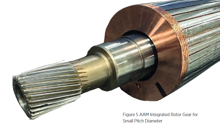
Higher motor speeds require higher gear ratios to maintain normal wheel speeds. Any ratio can be accommodated with enough successive reduction stages. However, each additional stage adds cost, mass, package space and parasitic loss to the gearbox. Typical low-speed drive units employ a 2-stage reduction. As such, it is desirable for a high-speed motor to avoid the penalty of adding a third reduction stage. The critical enabler for high ratio (up to 22:1) is keeping the first stage drive gear very small. By keeping the motor off the wheel axis AAM enables the rotor shaft drive gear pitch diameter to be very small to provide a large reduction in the first stage and reduce pitch line velocity (Figure 5)
Inverter
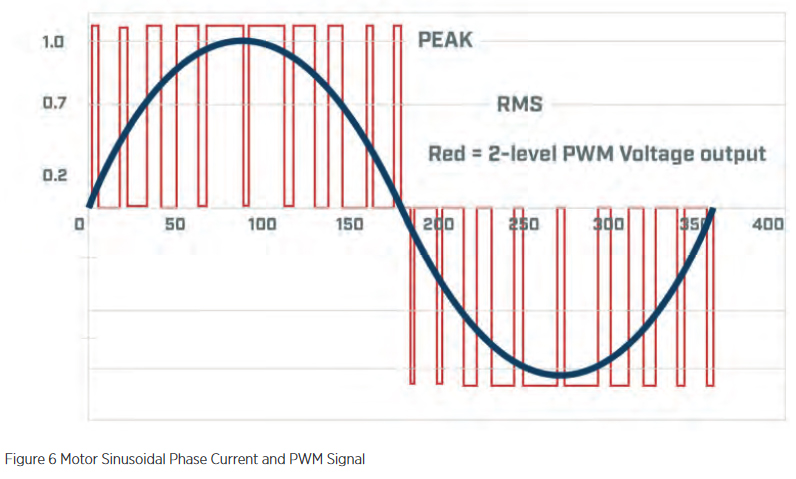
The inverter converts DC battery voltage into multi-phase AC that drives the stator of the electric motor. The frequency of the required sinusoidal current is directly proportional to the motor’s rotational speed and its number of magnetic poles. The inverter induces this sinusoidal AC to flow in the stator windings using pulse-width modulation (PWM) of the battery voltage (Figure 6). Pulse-width modulation involves solidstate switching devices that can turn on and off very quickly. Each on/off cycle results in a small amount of energy being lost within the switching device. As such, higher sinusoidal frequencies require faster switching, which increases inverter losses.
AAM’s 4-pole motor design operates at half the sinusoidal frequency of a traditional 8-pole motor. This enables the motor to spin at twice the speed with equivalent inverter switching losses.
Conclusion
AAM continues to push the limits of electric motor speed in EDUs. The company has several demonstration vehicles and one pre-production application running at 24,000 rpm, with an additional development unit producing 30,000 rpm. These designs can be produced at low cost in high volume using practical engineering solutions overcoming previously perceived limiting factors. These designs can enable the growth of EDUs into a wide variety of vehicle applications, thus creating a broader impact on carbon reduction and clean transportation. Innovations at AAM are creating efficiencies for our customers, satisfaction for consumers and an increased opportunity to positively impact our environment.
