Mathias Deiml, AVL Software and Functions GmbH
Katharina Berberich, AVL Software and Functions GmbH
Wilhelm Vallant, AVL List GmbH
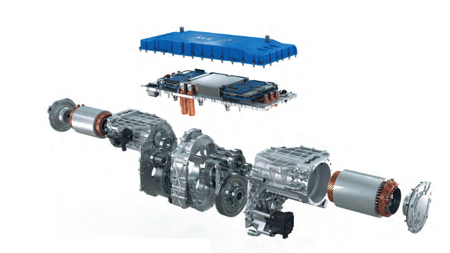
The e-mobility market is facing the challenge of an increasing pressure to reduce unit costs and increase power density and performance at the same time. AVL’s second-generation high-speed e-axle increases power density to reduce material usage, focusing on the e-motor and gearbox, with CO2-equivalent footprint as a key comparison criterion.
With the updated design in Generation 2 it achieves a power density of over 4.3 kW/kg, features a 30,000rpm motor, silicon carbide double inverter, and loss optimized gearbox. It minimizes magnet and copper use, reducing unit costs, CO2 emissions and improving efficiency.
Speed and cost – Why 30.000 RPM
Electric motors, such as PMSM based machines widely used for automotive applications, consist of high masses of expensive materials: dynamo sheet metal, magnets, copper. Reducing the size of the motor reduces these costs. Downside of this characteristic is that scaling down motor size means to reduce its torque.
Pmech = ω * M; M ~ d 2 * l;
d: diameter; l: lamination length
To maintain the power rating the rotational speed needs to be increased when reducing motor dimensions. An increase of factor 2 in motor speed results in a reduction of active motor material by a factor of 2. Provided that special or expensive technologies in motor and transmission can be avoided there is a substantial cost saving in the motor. Weight and size of the motor can be reduced accordingly and are additionally beneficial for vehicle features and again costs.
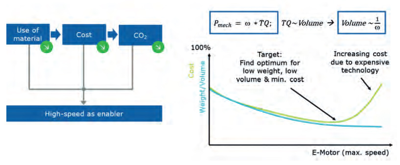
Fig. 1: Speed vs Cost
These relations between speed and weight/volume/cost are shown in Fig. 1. AVL’s engineers were looking
for the optimal speed, at which weight and cost are both low [1] and found it at 30.000 RPM.
High speed e-machine development
To develop this e-motor for the required 30.000 rpm without using expensive technology like cobalt steel lamination, the following challenges had to be overcome:
- Mechanical rotor strength due to high centrifugal forces
- Bearing technology at high rotational speed in partnership with SKF
- High frequency losses in copper windings
- Increased iron losses due to higher fundamental frequency of 1500Hz
The developed Solutions included new innovative designs for
- Hairpin Windings
- Cooling concept
Selecting hairpin winding technology helps to deal with the high frequency losses: A six-layer hair pin winding with bended copper on one side and copper forming and welding on the other side was chosen. A copper fill factor of 60% was achieved. This factor includes the oil channels for cooling, described in the cooling chapter. A slot-liner with only 0.1 mm thickness was used. The slot was optimized for coolant flow in combination with copper fill factor.
There is no need for resin in the slot. Thus, additional micro-oil channels along the copper improve coolant flow. Recycling of copper is facilitated; the winding can be removed in one piece without shredding. [2]
The prototypes were manufactured using SLM selective laser melting, a 3D copper printing process. This has further advantages:
- Smaller winding heads possible
- Low cost for tooling
- Smaller resistance compared to welding
Copper printing, may be only the beginning, further optimizations like free shaping of super short winding heads can be realized in later steps. It is suitable for small series production. For large scale volumes welding shall be used. AVL’s current design enables both manufacturing processes. [2]
The sophisticated direct cooling concept shown in more detail:
Direct oil cooling means that the coolant is directly in contact with the copper winding in the slots and winding heads. The stator is fully filled with oil, which is pumped along the stator slots. Thus, the copper losses are very efficiently cooled. An air gap tube keeps the oil away from the rotor space, so no friction or splashing losses are present. [3]
The transmission uses a dedicated lubrication fluid with an own oil pump and filter. In addition – compared to Gen 1 – there is now a transmission fluid cooler integrated. This device can be installed optionally, for high performance application, where it is needed. [2]
The magnets are cost-effective quality with low heavy rare earth content.
Achieved eMotor performance
The efficiency map shows a maximum of over 97%, in a wide range. Due to NO20, segmented magnets and high copper fill factor the losses at high speeds are well balanced. This is shown in Fig. 2.
The map is generated for 180°C copper temperature. Thanks to direct oil cooling, the copper temperature is typically 90°C, resulting in ever better efficiency.
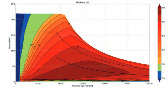
Fig. 2: High Speed E- Machine Performance and Efficiency at 180° C Machine Temperature
Overall EDU system implementation
The EDU design with the new e-Motor continued to focus on overall cost reduction, reduction of material usage and increased power density without losing efficiency. Scalability and high-volume rollout were also key considerations. With these requirements the resulting concept is described:
1. EDU:
a. dual motor, dual torque path to enable torque vectoring for premium segment
b. central gearbox for optimal length of drive shafts in
various vehicles
c. low profile design to support flat chassis
2. High speed motor:
a. standard materials for sheet metal and magnets
b. PSM technology for best power density and system efficiency
c. high frequency winding for low factor AC_loss / DC_loss
d. cooling with best-in-class effectiveness, combined with the inverter
e. mechanical rotor stability up to 1,2 * n max
3. SIC inverter:
a. high power density in complete package
b. best efficiency, fast switching slopes, variable switching frequency
c. combined DC link, interleaved switching, low EMC emissions
4. Gearbox:
a. 2 stage transmission, single speed
b. lay shaft concept
c. high efficient tooth geometry, optimal NVH tradeoff
d. injection lubrication, separate fluid than motor
CO2e footprint and comparison to other systems for AVLs e-axle technology
Besides the already discussed technological and cost targets, a future proven EDU concept must also comply to a sustainable design to reduce CO 2 e footprint and increase efficiency in the life cycle.
„Design-to-CO 2 e“ as a holistic approach in the course of the systems engineering meant a transition from an original focus on „design to function“ and „design to cost“, to the additional dimension of CO 2 equivalent over the life cycle. [4] The total life cycle includes Production, Use and End of Life with. recycling or 2 nd life.
Cost, weight & CO 2 e comparison
To compare our EDU system with different solutions, three systems with a peak power rating of 160 kW were evaluated: a baseline PMSM system, AVLs new high-speed PMSM system, and an externally excited synchronous motor (EESM) system.
For the complete EDU system, the evaluation included weight, cost, and CO 2 e of active motor parts, power inverter, and transmission, considering additional components like rotor shaft, bearings, and motor housing. Rotor excitation for the EESM system is considering cabling, sensors, and rotor interface as part of the power inverter.
Collector ring and copper bars/wires to the rotor windings are already considered with the E-Motor active parts. A potential for saving in terms of weight and cost was identified in the magnitude of 17 kg and 8% respectively with the use of high-speed motor, where EESM shows the potential of 5% cost saving but a disadvantage of up to 13kg in terms of system weight (see Fig. 3).
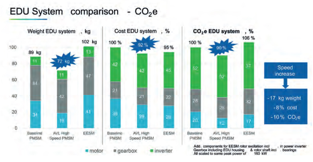
Fig. 3: Weight, cost & C0 2 e evaluation – EDU System
Evaluating the sustainability of EDU systems by comparing calculated CO 2 e emissions shows an advantage
of 10% with the High Speed PMSM System and a potential increase in terms of CO 2 e emissions of up to 6%
with the EESM system. [3]
Conclusion and outlook
AVL’s high speed EDU is in the second generation with an efficiency and performance above state of the art and improved sustainability due to high power density of 4.3kW/kg.
The described technology is tested continuously, e.g. in 2 AVL demo cars, which are running since 2020. Furthermore, the AVL torque vectoring function has been developed for and demonstrated in the vehicle.
Planning of our Gen 3 includes further improvement of inverter power density by 50%, a single motor derivate EDU for compact cars with only 25kg at 120kW/3400Nm, and intensive use of AI based machine control, such as rotor temperature determination.
References
[1] M. Deiml, A. Simonin, P. Jafarian: High Speed Electric Drive by AVL, CTI Berlin, 2018
[2] M. Deiml, M. Schneck: Increasing the Sustainability of Electric Drives by High Speed Motor Technology, CTI Berlin, 2022
[3] A. Angermaier; M. Deiml; W. Vallant; G. Fuckar:, Electric drive units with high power density and sustainability through high speed and maximum efficiency, Wiener Motoren Symposium, 2024
[4] Sams, C.; von Falck G.; Sorger H.: Cost Engineering as an Essential Part of Systems Engineering. In Systems Engineering for Automotive Powertrain Development. Schweiz: Springer, 2021