Dr. Jörg Gindele, Senior Director Business Expansion & Transformation, Magna Powertrain
Other than combustion engines, electric motors benefit from up- instead of downsizing. When intelligently combining them in an all-wheel drive, efficiency can be further increased, and especially by implementing a ‘complementary’ e-drive topology.
With combustion engines, we have become accustomed to the idea that downsizing concepts with increased engine load can help to reduce fuel consumption. In contrast, electric motors usually work most efficiently at partial loads. This is one reason why seemingly overpowered e-drives can be even more efficient. This applies even more when combining the e-drives over two axles in an electric all-wheel drive system (eAWD). When intelligently combining the efficiency maps of both motors and adding a decoupling option, eAWD can even be superior to a two-wheel drive system. The formula uses three levers: powerful e-motors, a decoupling system, and a ‘complementary’ e-drive combination.
Magna examined six in-house e-drives from 105 to 250 kW to examine the effect of increasing the power. It could be found, that while losses from the inverter and the gearbox vary only slightly, the e-motor losses become significantly smaller with increased output. The comparison was made with identical boundary conditions, i.e. 800 V architecture, SiC inverters, and the simulation performed in the WLTC.
Losses of electric drives
Comparing these six drives resulted in the findings illustrated in Figure 1: The inverter losses remained largely constant for all variants. The data showed somewhat greater differences in the transmission losses. The losses increase slightly with higher available maximum torque of the drive, but on the other hand, the more powerful motors allow for transmissions with longer ratios and thus reduced losses.
It is particularly noticeable that with increasing motor power, the e-drives have lower motor losses in the WLTC. This is because they can operate in a more efficient map range to handle the load. In simple terms, many e-motors have their best load points at around 30 percent of the load, while internal combustion engines often have their sweet spot at around 70 percent.
This means effectively that electric drives need no load point up-shifting in the familiar sense. On the contrary, the aim will be to bring the low-load efficiency sweet spot into congruence with typical operating points in the WLTC and real traffic situations like motorway driving.
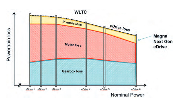
Figure 1: E-motor losses within the powertrain become smaller when increasing power output.
Shifting the efficiency map of e-motors
To illustrate this, the efficiency-optimized operating range of the e-drive and the relevant operating points are shown in raltion to e-drive axle speed and axle torque, Figure 2. The relevant operating points are derived from the WLTC – and supplemented by highway driving since this can include higher speeds, especially in Germany.
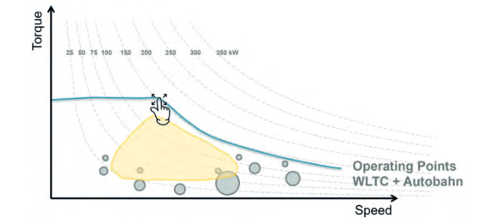
Figure 2: Typical offset of efficiency map and operating points with a small e-motor
The e-drive output torque is plotted on the y-axis, and the output speed is on the x-axis. The blue line indicates the peak torque curve including the corner point, which defines the maximum torque and power. The area in which the efficiency of the motor is at least 92% is shown in yellow. The grey circles indicate typical operating points in the WLTC and during highway driving, their diameter indicates the frequency of use. It is important to note that operating points at higher speed and higher torque are particularly significant as they result in increased losses.
 The diagram illustrates an electric motor with a rather low power output. As can be seen, the operating points largely do not match the beneficial efficiency range. This especially applies to the operating points at higher speed and with a high frequency of use and thus a high effect on energy consumption. The aim is therefore to shift the sweet spot towards these points.
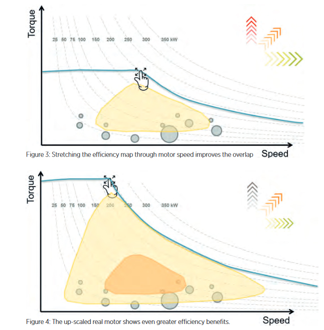
If you now increase the power by increasing the torque while maintaining the motor speed, the sweet spot moves away from the operatin points. If, on the other hand, the power is increased via a moderate torque increase and increasing the motor speed, the sweet spot includes more operating points, especially at higher speeds. Even better coverage can be achieved if the power increase is made only via the speed so that the sweet spot includes a large part of the operating points, Figure 3.
In general, it can be seen that a larger sweet spot and thus better coverage with the operating points can be achieved with the more powerful motor. To which extent increasing the power by torque and/or speed is the best way, requires a specific look into the vehicle application and the electric motors available. There is always a specific trade-off between torque and speed.
Interestingly, it could also be seen for real-world e-motors that, when power is increased, the peak efficiencies continue to increase due to component effects. Electric motors designed for higher power output contain more copper and laminated iron materials. This results in a reduction of losses in the partial load range, Figure 4. Even with a power increase by more torque, the important operating points in the cycle and on the highway can be covered.
What this means for eAWD architectures
When scaling the range of BEVs, more electric power is necessary, because the batteries add considerable weight. It makes sense to distribute this power over two axles, the more so as this will improve traction and driving dynamics. However, as will be shown further below, an even higher efficiency can be achieved than with a 2WD vehicle through an intelligent “complementary” use of both primary and secondary of the eAWD system.
Figure 5 shows all the drive configurations investigated. The topologies range from 2WD to non-optimized AWD solutions, to those further optimized by decoupling systems, and finally to complementary drive designs.
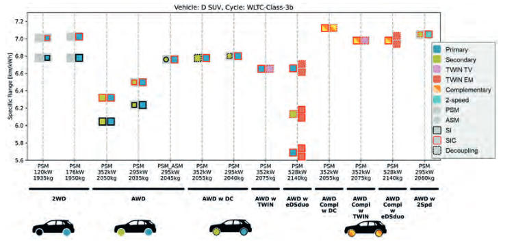
Figure 5: Efficiency results of the drivetrain configuration compared
First, two 2WD drives with 120 and 176 kW are shown on the left. The above drive in each column has a SiC inverter, enabling a powertrain efficiency improvement of approx. 2%. It can be seen in the second column that, contrary to “traditional” thinking, the more powerful drive offers higher efficiency.
Following on the right, only AWD architectures are shown. As expected, a configuration with two PSMs on the front and rear axles has increased losses. This is because the PSM cannot be deactivated, and is causing electrical losses. Both e-motors must work together permanently, restricting the operating strategy design.
A quite common solution is using a secondary axle with an ASM and a PSM at the primary axle. Magna Powertrain’s ASM secondary drives are optimized for minimal drag losses through the implementation of a sophisticated bearing concept, resulting in low mechanical losses during standby operation. The ASM is only used as a boost axle here; the PSM primary drive can be designed for optimum efficiency in lowload situations.
Two PSM solutions with mechanical decoupling
Another option is to use a PSM with a mechanical decoupling device instead of an ASM on the secondary axis. In the Magna decoupling system, a lossless dog clutch is utilized to decouple the PSM. The switching times are so short that the system can be integrated into the operating strategy transparently and without any functional disadvantages [2].
Moreover, Magna has looked at the following secondary drives for AWD architectures: The Twin EM axle system uses two electric motors with summed up power, again with two decoupling elements. This allows for lateral torque vectoring and lossless decoupling, too. However, the available torque for torque vectoring is lower than with a single motor with a downstream torque vectoring element.
Magna Powertrain’s Twin TV (Torque-Vectoring) drive operates with only one electric motor but features two wet clutches for lateral torque distribution. The (normally) open state of the clutches corresponds functionally to the decoupling function as described above. Drag losses of the clutch system are minimal thanks to increased air gaps and oil ejection. Compared to the variant with two motors, the advantage of this solution is that the torque of the single motor can be shifted entirely. Moreover, it is comparatively cost-effective.
Further benefits through complementary drives
When comparing the AWD variants described above, it can be seen that they are all close to an optimized 2WD drive in terms of efficiency. This confirms the assumption that AWD is preferable, as it comes with additional functional benefits. So far, however, this effect is mainly dominated by the higher power output and the resulting load reduction.
Complementary drives will enable a further efficiency increase. The concept of a complementary drive includes the integration of two distinct electric drives, each having unique advantages. One approach to realizing the concept of complementary drives is combining a front axle with a long gear ratio and a rear axle that can be decoupled. The front axle‘s gear ratio is selected to cover the efficiency-optimized range for relevant highway operating conditions. Figure 6. As a result, the front axle exclusively handles constant highway driving.
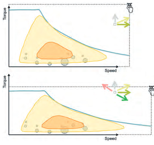
Figure 6: A longer ratio enables to improve the coverage of sweet spot and operating points.
Dynamic driving in the lower speed range is performed using both axles to maintain low load points. The e-motors are specifically optimized for these operating points to fully utilize the efficiency potential. The resulting reduced wheel torque of the front axle is compensated for by the second drive, which is dominant for wheel torque and traction when boosting (the secondary drive is located on the rear axle).
The savings are achieved in operating phases that are relevant for consumption, i.e., at constant speed, which is usually associated with more distance traveled. All three AWD variants considered in the complementary design even exceed 2WD efficiency by 2-3%. Which of the variants is preferable, mainly depends on functional requirements.
The overall result is that an intelligently designed complementary AWD is significantly more efficient than a 2WD drive, while including significantly increased customer benefits in terms of traction, driving dynamics, and vehicle controllability.