A Holistic System Optimization of BorgWarner’s Next Generation Integrated Drive Modules
Dr. Arnaud Leblay, System Engineer Technologies & Innovation
Eric Bourniche, Engineering Supervisor Technologies & Innovation
Dr. Pascal David, Engineering Manager Technologies & Innovation
Adrien Bossi, System Engineer Technologies & Innovation
Harsha Nanjundaswamy, Engineering Director Technologies & Innovation
all BorgWarner PDS
1. Introduction
The development of cost effective, energy efficient and reliable Integrated Drive Modules (iDM) for electric vehicles is closely tied to optimization challenges. Addressing these challenges requires Multiphysics holistic approaches, that span magnetic, electrical, thermal, mechanical and fluid domains. Such an engineering methodology has been adopted by BorgWarner.
Across the industry, numerical methods such as Finite Element Analysis (FEA) and Computational Fluid Dynamics (CFD) are widely used to evaluate systems involving one or more physical phenomena within multiphysics analyses. These Tools form the foundation for higher level modeling approaches such as Digital Twins, which enable full system vehicle simulations and the evaluation of electric machine control strategies under real driving conditions. Combined, these Methods provide critical metrics that support decision making and guide technology development roadmaps.
BorgWarner PowerDrive Systems Technologies & Innovation group has developed a high fidelity, multiphysics based Digital Twin to support the development and innovation of iDM. The model has been rigorously validated through comparison with 78 physical signals sourced from both CAN communication channels and external sensor data [1]. In addition, some numerical models of sub components have been developed and validated in partnership with universities.
2. Methodologies Development for Deeper Insight
Methods form the foundation of engineering organizations. Sustaining innovation requires continuous improvement. Our methodology development strategy is grounded in in-house technical excellence, with experts actively contributing to Centers of Expertise to share best practices, lessons learned and identify improvement opportunities. This internal capability is further reinforced through strategic partnerships with academic institutions, start-ups, and technology providers. Our Analytical Simulation Design plan [1] is formed by simulation Cards whose inputs and outputs are bound to other cards to form a structured simulation framework. It enables pinpointing methodological gaps and areas where model predictions need refinement for greater accuracy and highlights phenomena that require deeper investigation through multiphysics analysis.
Those refinements are based on a dual approach combining advanced multiphysics modeling with high-quality experimental validation. The refinements can focus non-exhaustively on thermal, electric, magnetic, mechanical or fluid dynamics behaviors on overall iDM and its subcomponents.
One of these approaches concerns the methodology refinement applied to electric machine stator loss assessment. Stator loss can be split into iron loss and copper loss. The loss estimation enhancement is performed in collaboration with the Division of Industrial Electrical Engineering and Automation of Lund University in Sweden. The study was carried out in multiple steps to characterize the material properties, model the electromagnetic behavior, and finally perform transient thermal analysis.
The first step of the loss evaluation is to measure the lamination loss named iron loss and magnetic properties as magnetic hysteresis curves also known as BH curves. The experimental description can be found in [2].
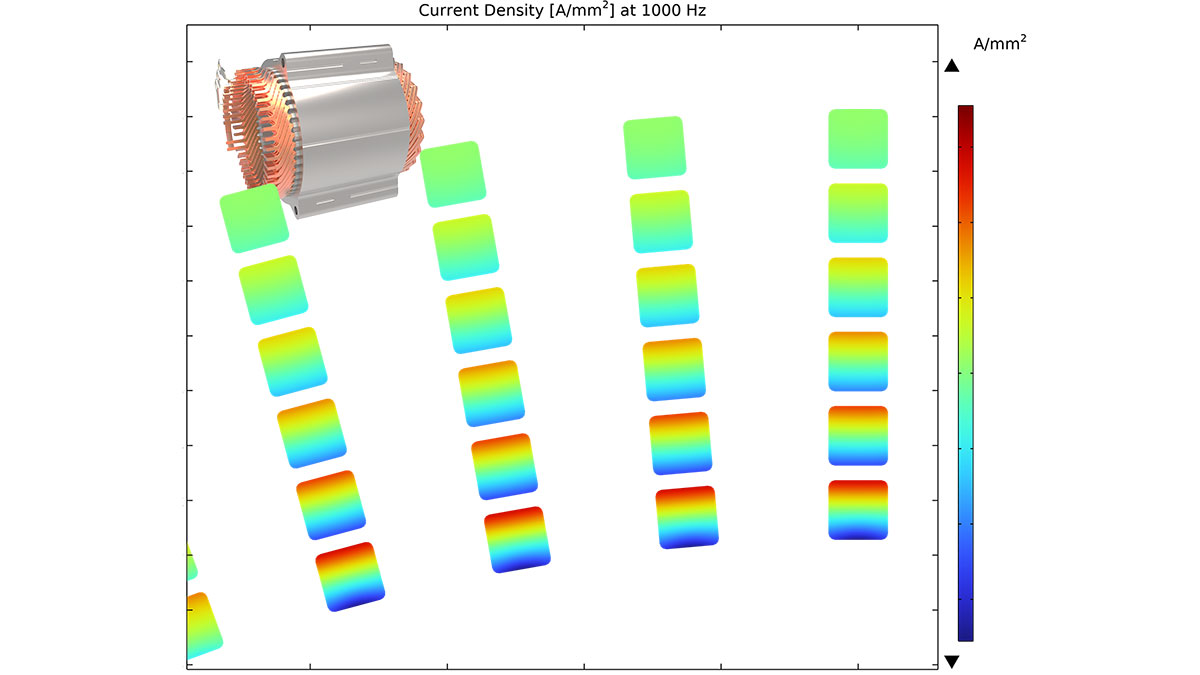
The second step involves using the magnetic properties obtained in the first step and incorporating them into 3D Finite Element (FE) model of a complete wound stator under COMSOL Multiphysics, to assess the copper loss. The simulated impedances are compared to impedances measurements, and the relative error is not higher than 5% over a range of 100 Hz to 10 kHz.
The resulting current density with the conductor cross section can be observed on Fig. 1. The current density is not equally distributed resulting in the difference of losses within the conductors. A coupled electromagnetic thermal model was then employed to perform a transient analysis under adiabatic boundary conditions with the surrounding environment. The resulting temperature distribution after a 30 s transient event is presented in Fig. 2.
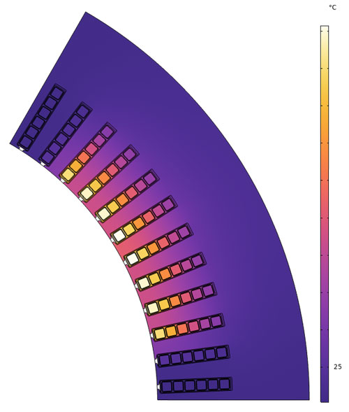
Figure 2: Temperature distribution after 30 s transient heat up in adiabatic conditions at 200 A(peak) and 1000 Hz
At system level, the inverter generates the current waveforms required to control the electric machine’s performance and control strategies are developed accordingly to enhance overall system behavior. Using the previously detailed multiphysics approach enables a precise assessment of how those current waveforms impact electrical machine losses. This capability permits us to optimize the influence of innovative control strategies at inverter level on vehicle efficiency as demonstrated in [1], as part of our model driven innovation and optimization capability.
3. Model Driven Innovation and Optimization
Innovation and optimization of the iDM are supported by several key pillars. One of them is Process and Design Development. Process and design tools are evolving in parallel, allowing engineers to explore innovative geometries and structures that were previously unattainable. Such optimization has been performed for a heatsink used in a power electronincs device, resulting in complex geometry as shown on Fig.3. A cooling liquid is turbulently flowing inside the heatsink to cool two heat sources. The topology optimization has been set to minimize the temperatures of the heat sources and their temperature differences, while being below a pressure drop threshold. It defines the inner geometry. The synergy between 3D metal printing and numerical multiphysics topology optimization has become a key driver for innovative solutions.
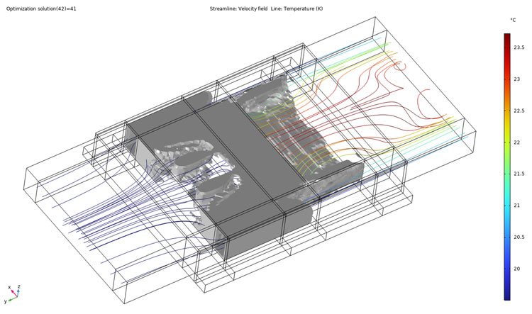
Figure 3: 41st iteration of 3D topology multiphysics optimization with a turbulent flow and two heat sources at the lowest surface
A second pillar is driven by AI breakthroughs in materials development. Historically, geometry/function and material selection have always been closely intricated in the development of components. Recent progress in artificial intelligence has significantly accelerated the growth of Computational physics, chemistry, and materials science. These approaches leverage quantum mechanics to predict the atomistic structure of materials and translate it into macroscopic physical properties. Machine‑learning‑based computational physics now enables tailoring a material’s atomic structure to meet specific performance requirements [3].
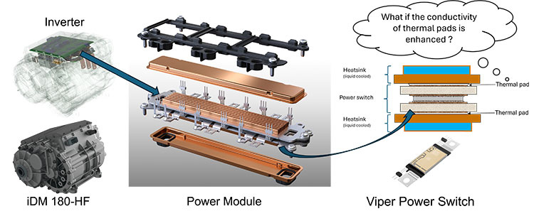
Figure 4: Integrated Drive Module iDM 180-HF, illustrating the inverter, its liquid cooled power module and its Viper power switches.
The third pillar is enabled by Digital Twin, which builds upon the first two approaches to optimize physical components and reinforce system‑level foundations. This pillar focuses on the development and evaluation of innovative control algorithms and new iDM control strategies [4]. Although the inherent complexity of the vehicle system impacts Simulation time, preliminary insights can often be obtained within only a few electrical cycles. While advanced control algorithms can be evaluated on a millisecond timescale, the full potential of Digital Twins is realized when combined with Reduced Order Models (ROMs), which significantly
accelerate simulation performance.
4. Use Case
The Digital Twin methodology makes it possible to extract high level, system wide performance indicators while still capturing the detailed behavior and interactions of individual components. Fig.4 illustrates this multiscale capability by zooming from the overall iDM architecture comprising the inverter, electric machine, and transmission, down to ist subcomponents. Within the inverter, for example, the power module is modeled at a granular level. It consists of a stacked assembly that typically includes heatsink, thermal interface material (such as a thermal pad), and the power semiconductor switch. This detailed representation ensures that local thermal electrical behavior including parasitic phenomena are accurately captured and propagated up to system level performance metrics.
In this study, a vehicle Digital Twin embedding all multiphysics complexity into one single environment is employed. Electric machine, inverter and transmission models are interconnected and brought into a full vehicle representation. This includes detailed, non-exhaustively, thermal management, intelligent control strategies, thermal models, cooling system, lubrication.
Based on the vehicle Digital Twin simulation over a WLTP cycle, the results presented in Fig. 5 demonstrate the benefit of combining detailed component-level analysis with a system-level approach to assess global performance indicators.
The power switch temperatures can be accurately estimated at both granular and helicopter views. The evolution of the maximum power switch temperature over a single WLTC for three different thermal conductivities of the pad can be evaluated. The temperature profile exhibits alternating peak and cool‑down phases, driven by several factors such as instantaneous current demand, DC-link voltage, switching frequency, and the applied control strategies. In addition, the absolute power losses are strongly influenced by the semiconductor die Technology itself, which affects both switching and conduction losses. While many studies assume a constant coolant temperature at the heatsink inlet, vehicle thermal management has a major impact on component thermal behavior. Radiator valve actuation, front fan operation, and the overall thermal Management architecture and control strategy directly influence the inlet coolant temperature evolution. Consequently, these effects lead to different maximum temperature levels for the power electronic components, highlighting the importance of a fully coupled electro‑thermal‑system simulation approach.
5. Conclusion
The development of new numerical methodologies, validated through experimental investigations, enables a deeper understanding of coupled field effects, such as fluid, mechanical, thermal, electric, magnetic, and parasitic phenomena, and their impact on system behavior. By combining detailed component level multiphysics models with vehicle level driving cycles, BorgWarner’s Digital Twin provides system wide performance indicators while preserving physical fidelity. This capability transforms simulation from an analysis tool into a decision making and optimization platform for architecture selection, material choices, and control strategies. The ability to assess component-level impacts at granular view while simultaneously maintaining a helicopter view at system level is a key enabler for rapid innovation and robust holistic optimization.
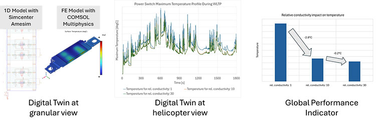
Figure 5: Overview of Digital Twin capabilities from granular to helicopter view providing global performance indicators at vehicle system level.
Sources:
[1] Bossi, A., Bourniche, E., Leblay, A., David, P. et al., „Digital Twin, A Multiphysics Numerical Tool Chain for Next Generation Electric Drive Design,“ SAE Technical Paper 2025-01-8624, 2025.
[2] Colombo, L., Reinap, A., Fyhr, P., Alaküla, M., „Enhancing Core Loss Tracking Accuracy in Stator Cores: A Comparative Assessment of Static and Dynamic Jiles-Atherton Model Formulations,“ IEEE Transactions on Magnetics, vol. 61, no. 8, pp. 1-12, Aug. 2025, Art no. 7300512
[3] Boziki, A. “HPC in Physics: Enabling Simulations and Accelerating Data Processing,” Presentation at SCynergy, April 2025.[3]
[4] Nanjundaswamy, H., Deussen, J., Mayer, A. et al., “A Step Beyond Two, “Next Generation Multi-Level Traction Inverter with Clean Wave Technology”, 46th International Vienna Motor Symposium 2025, ISBN: 978-3-9504969-4-9